
Mattaus
Flashlight Enthusiast
Hi all :wave:
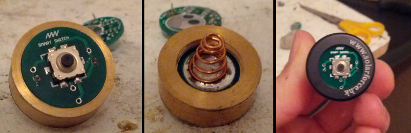
Introducing the SmartSwitch - a high power, low resistance, dual momentary flashlight clicky switch.
Physical Details
There are 3 versions of the smart switch:
Z41 ULP Switch
The Z41 ULP SmartSwitch is an ultra-low-profile switch that once installed consumes less than 7mm of battery space (boot and spring included). This is ideal for use in setups that require maximum utilization of the tube space available. Due to the physical design of this switch it is only compatible with Z41 tail caps or similar.
Z52 Switch
The Z52 SmartSwitch is a direct replacement for a McClicky switch and shares the same physical dimensions and threading properties.
Z57 Switch
The Z57 SmartSwitch is compatible only with SureFire Z57 clicky tail caps.
Electrical Details
While the physical packaging of the 3 switches are different, the functionality and electronics of the switches themselves are identical. The details are as follows:
The 3 day switching time is based on the user actively holding the switch in. If the user has permanently turned the switch on and then released the switch (so the light is still on) the MCU returns to a deep sleep mode. If you had a main battery large enough you could turn this switch on once and it would run for over 10 years. Simply put, under normal operating conditions 3 days is the absolute worst case scenario, with typical use far exceeding this time.
Testing completed at this point in time (2.5 months of daily use) has revealed that the coin cell is yet to drop below 3V. Despite having been in use for 2 months, this cell is effectively brand new.
* I strongly recommend that the MOSFET ratings are not pushed too hard, with safe usage theoretically being around 10V/15A.
Theory of Operation
People seemed to like VanIsle's FETtie switch. In principle it was a great idea. However I saw a few reported issues with it and after doing a bit of research it boils down to the following.
FETs have a turn on Voltage (Vgs) which when reached means the FET is fully on. At this fully on state the resistance from the Drain to Source (Rds - basically the resistance between the flashlight host and the battery negative terminal) will be at its lowest. This value differs from FET to FET. MOSFETs will start switching on even if Vgs is not reached. At this lower on-voltage Rds is increased. With increased resistance comes an increase in power being burnt off as heat. FETs can only handle so much power before they go up in smoke. The FET used by the FETtie, whilst capable of turning on properly with voltages as low as 3V, does not actually turn on properly much lower than that. So while the FETtie would have worked perfectly on a fresh cell, not long after first use it would have slowly started cooking itself. The more the coin cell is allowed to deplete, the worse the situation gets.
Eventually every FETtie would fry itself unless the coin cell was replaced reasonably regularly.
So the key was to find a FET that can turn on properly at sufficiently low voltages for this application. The FET the SmartSwitch uses guarantees full turn on at 1.8V. In order to ensure the switch doesn't attempt to operate at too low a voltage, a microcontroller has been incorporated to monitor the voltage of the coin cell. Once a low voltage threshold is reached the SmartSwitch will dim and return to full brightness 0.5s after it's turned on, and then once every 2s. This warning is only present while the switch is actively pressed. To allow for any errors in the accuracy of the voltage readings, the low voltage cut off in the SmartSwitch is 1.9V.
There is a secondary advantage to having a microcontroller/MOSFET pairing inside the switch - we can have forward AND reverse momentary action. No more picking one or the other :thumbsup:
The switch is basically the same as used in digital cameras. The momentary action (opposite of the current permanent state) is enacted with a half press and a permanent action is enacted with a full press. It's totally different to a McClicky as there is a very distinct difference between the momentary and permanent action. Operation of momentary mode is near silent, with a permanent press being audible, but nowhere near as loud as the click of a conventional switch. The best example of this type of switching would be the pre-focus on a digitial camera.
Proof of Concept and Functional Demonstration
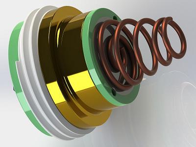
Z52 Render
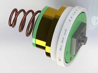
Z57 Render
As always any questions, comments, and suggestions are encouraged.
Thanks,
- Matt
Introducing the SmartSwitch - a high power, low resistance, dual momentary flashlight clicky switch.
Physical Details
There are 3 versions of the smart switch:
Z41 ULP Switch
The Z41 ULP SmartSwitch is an ultra-low-profile switch that once installed consumes less than 7mm of battery space (boot and spring included). This is ideal for use in setups that require maximum utilization of the tube space available. Due to the physical design of this switch it is only compatible with Z41 tail caps or similar.
Z52 Switch
The Z52 SmartSwitch is a direct replacement for a McClicky switch and shares the same physical dimensions and threading properties.
Z57 Switch
The Z57 SmartSwitch is compatible only with SureFire Z57 clicky tail caps.
Electrical Details
While the physical packaging of the 3 switches are different, the functionality and electronics of the switches themselves are identical. The details are as follows:
- MOSFET based switch
- Forward and reverse momentary operation
- Microprocessor controlled
- CR1025 3V Coin cell powered
- MOSFET rated to 20V and 30A absolute maximum*
- Coin cell voltage monitoring
- In standby mode the switch will last over 10yrs.
- In active mode the switch will last the equivalent of leaving a light on for 3 days straight.
The 3 day switching time is based on the user actively holding the switch in. If the user has permanently turned the switch on and then released the switch (so the light is still on) the MCU returns to a deep sleep mode. If you had a main battery large enough you could turn this switch on once and it would run for over 10 years. Simply put, under normal operating conditions 3 days is the absolute worst case scenario, with typical use far exceeding this time.
Testing completed at this point in time (2.5 months of daily use) has revealed that the coin cell is yet to drop below 3V. Despite having been in use for 2 months, this cell is effectively brand new.
* I strongly recommend that the MOSFET ratings are not pushed too hard, with safe usage theoretically being around 10V/15A.
Theory of Operation
People seemed to like VanIsle's FETtie switch. In principle it was a great idea. However I saw a few reported issues with it and after doing a bit of research it boils down to the following.
FETs have a turn on Voltage (Vgs) which when reached means the FET is fully on. At this fully on state the resistance from the Drain to Source (Rds - basically the resistance between the flashlight host and the battery negative terminal) will be at its lowest. This value differs from FET to FET. MOSFETs will start switching on even if Vgs is not reached. At this lower on-voltage Rds is increased. With increased resistance comes an increase in power being burnt off as heat. FETs can only handle so much power before they go up in smoke. The FET used by the FETtie, whilst capable of turning on properly with voltages as low as 3V, does not actually turn on properly much lower than that. So while the FETtie would have worked perfectly on a fresh cell, not long after first use it would have slowly started cooking itself. The more the coin cell is allowed to deplete, the worse the situation gets.
Eventually every FETtie would fry itself unless the coin cell was replaced reasonably regularly.
So the key was to find a FET that can turn on properly at sufficiently low voltages for this application. The FET the SmartSwitch uses guarantees full turn on at 1.8V. In order to ensure the switch doesn't attempt to operate at too low a voltage, a microcontroller has been incorporated to monitor the voltage of the coin cell. Once a low voltage threshold is reached the SmartSwitch will dim and return to full brightness 0.5s after it's turned on, and then once every 2s. This warning is only present while the switch is actively pressed. To allow for any errors in the accuracy of the voltage readings, the low voltage cut off in the SmartSwitch is 1.9V.
There is a secondary advantage to having a microcontroller/MOSFET pairing inside the switch - we can have forward AND reverse momentary action. No more picking one or the other :thumbsup:
The switch is basically the same as used in digital cameras. The momentary action (opposite of the current permanent state) is enacted with a half press and a permanent action is enacted with a full press. It's totally different to a McClicky as there is a very distinct difference between the momentary and permanent action. Operation of momentary mode is near silent, with a permanent press being audible, but nowhere near as loud as the click of a conventional switch. The best example of this type of switching would be the pre-focus on a digitial camera.
Proof of Concept and Functional Demonstration
Z52 Render
Z57 Render
As always any questions, comments, and suggestions are encouraged.
Thanks,
- Matt
Last edited:
")