
Epsilon
Enlightened
XM-L2 U2 7* XM-L
In succession to the 7* XM-L U2 in FiveMega Elephant II host:
A 7*XM-L2 U2 build in FiveMega Elephant II host in Blue!
Enjoy!
When I had the heatsink of the previous build made, I already had two hosts so asked for two heatsinks.
Most of the building is the same as this build, so for more detail information:
7*-XM-L-U2-in-FiveMega-Elephant-II-host-build-7000-Led-lumen-power-BEAMSHOTS-added!
So, the parts:

- XM-L2 U2 Leds on execellent Led-tech.de 16mm copper PCB's
- 7 Der-Wichtel 23mm reflectors
- Taskled.com HBFlex
- Aluminium heatsink with dremelled wire groves
- Reflector holder
- Template for LED placement (not a part, but a tool to position the LEDS on the heatsink)
- FiveMega Elephant II host in blue (not in this pic )
)
- 4*18650 battery pack (not on pictures, please refer to the 7*XML buildlog).
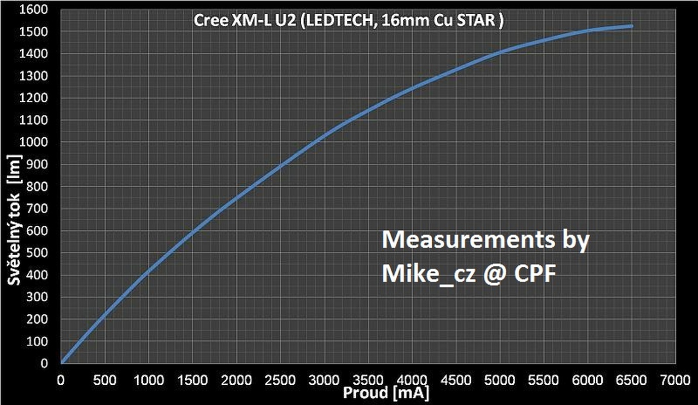
A graph of the XM-L version of the LED on the same PCB:
This graph is from a CPF user (added the credits) very well done. His topic here

Lapped heatsink


Glued the LEDS, soldered the wires and covered them with 3M Polyimid tape for electrical insulation.
Mounted the driver (filed slightly to fit the Mag-Lite size tube) with the supplied thermal tape

2mm gold contacts solderd to the driver.


Momentary mod on the Maglite switch

Mounted the other end of the 2mm gold contacts in the switch.
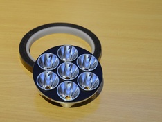

Hot glued the reflectos in the reflector holder

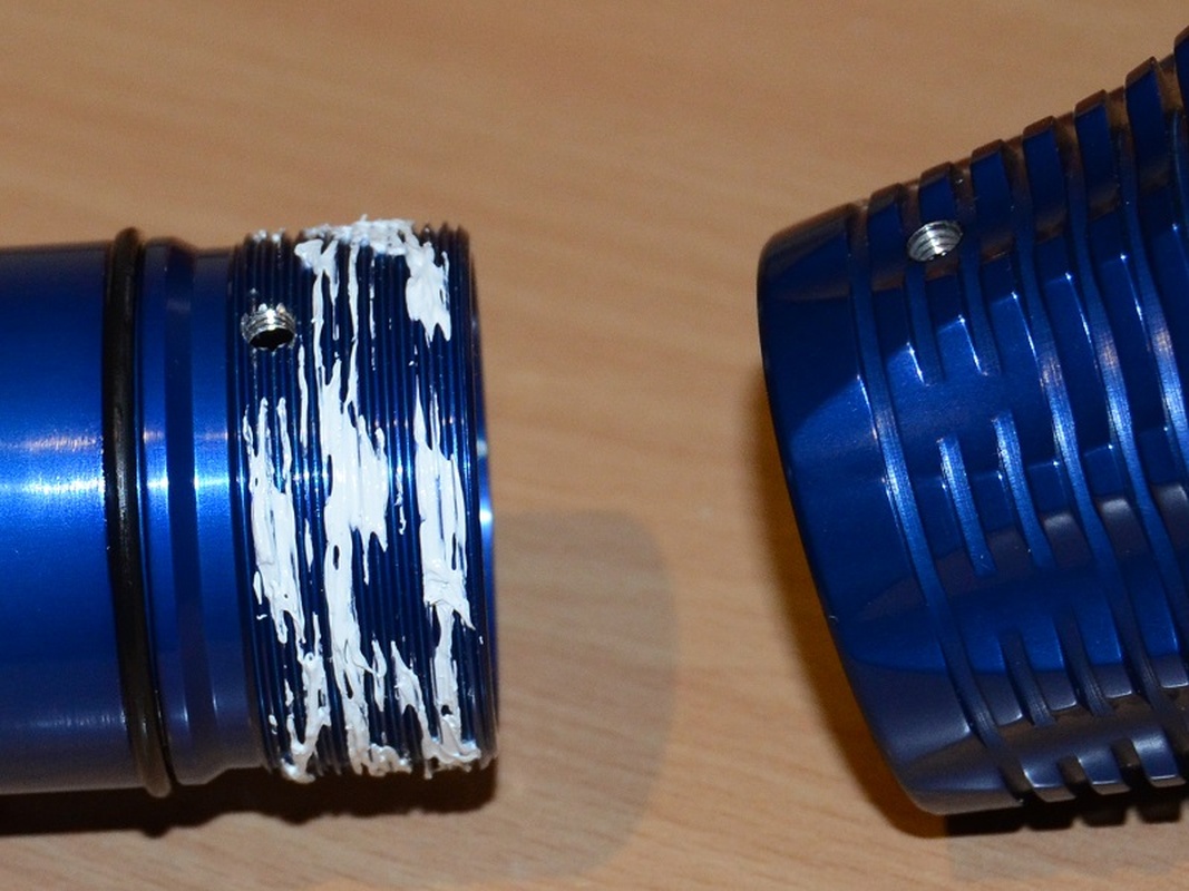
Applied some thermal paste to the threads to use the complete head as a heatsink and grease to the seal for water tightness and easy screw-on.
New Detail: I screwed the head on, drilled a hole and tapped the hole.
This will be used to secure the head when the light is together. This prevents the head to be (accidently) twisted of and causing damage to the light.
Time to put the light together!


Testfire with the battery in place.

The drop-in of the reflector assembly
The completed Light


Beamshots
And to finish everything off: BEAMSHOTS!
To compare the light, I made a new set of beamshots with the following lights.

Lineup (Right to left)
- DX Aurora 35mm reflector light which I modded with a better heatsink and XM-L T6 @ 2800mA
- FiveMega 18650 D36 with XM-L U2 @ 3.8A (see sig for more info)
- Megalennium 2*26500 with XM-L2 U2 @ ??? (wait for topic soon)
- Mag2D Rebel with XM-L2 U2 @ 4.5A (see sig for more infO)
- Light of this topic
Mag2D Rebel 4.5A XM-L2 topic: Two-Maglite2D-builds-XM-L-5000mA-vs-XM-L2-4500mA-Comparing-beamshots
old beamshots (Auto White-ballance) removed.
New beamshots (4000K fixed white ballance):


Hope you enjoyed the topic
26-Jan-2014 update: Temperatures (No airflow, lying on table, tempsensor with AA and insulated on the neck)
Note: Step4 is around is 1800mA
Note: 60DegC is a very conservative step-down setting.
In succession to the 7* XM-L U2 in FiveMega Elephant II host:
A 7*XM-L2 U2 build in FiveMega Elephant II host in Blue!
Enjoy!
When I had the heatsink of the previous build made, I already had two hosts so asked for two heatsinks.
Most of the building is the same as this build, so for more detail information:
7*-XM-L-U2-in-FiveMega-Elephant-II-host-build-7000-Led-lumen-power-BEAMSHOTS-added!
So, the parts:

- XM-L2 U2 Leds on execellent Led-tech.de 16mm copper PCB's
- 7 Der-Wichtel 23mm reflectors
- Taskled.com HBFlex
- Aluminium heatsink with dremelled wire groves
- Reflector holder
- Template for LED placement (not a part, but a tool to position the LEDS on the heatsink)
- FiveMega Elephant II host in blue (not in this pic
)- 4*18650 battery pack (not on pictures, please refer to the 7*XML buildlog).
A graph of the XM-L version of the LED on the same PCB:
This graph is from a CPF user (added the credits) very well done
. His topic here

Lapped heatsink


Glued the LEDS, soldered the wires and covered them with 3M Polyimid tape for electrical insulation.
Mounted the driver (filed slightly to fit the Mag-Lite size tube) with the supplied thermal tape

2mm gold contacts solderd to the driver.


Momentary mod on the Maglite switch

Mounted the other end of the 2mm gold contacts in the switch.


Hot glued the reflectos in the reflector holder

Applied some thermal paste to the threads to use the complete head as a heatsink and grease to the seal for water tightness and easy screw-on.
New Detail: I screwed the head on, drilled a hole and tapped the hole.
This will be used to secure the head when the light is together. This prevents the head to be (accidently) twisted of and causing damage to the light.
Time to put the light together!


Testfire with the battery in place.

The drop-in of the reflector assembly
The completed Light


Beamshots
And to finish everything off: BEAMSHOTS!
To compare the light, I made a new set of beamshots with the following lights.

Lineup (Right to left)
- DX Aurora 35mm reflector light which I modded with a better heatsink and XM-L T6 @ 2800mA
- FiveMega 18650 D36 with XM-L U2 @ 3.8A (see sig for more info)
- Megalennium 2*26500 with XM-L2 U2 @ ??? (wait for topic soon
)- Mag2D Rebel with XM-L2 U2 @ 4.5A (see sig for more infO)
- Light of this topic
Mag2D Rebel 4.5A XM-L2 topic: Two-Maglite2D-builds-XM-L-5000mA-vs-XM-L2-4500mA-Comparing-beamshots
old beamshots (Auto White-ballance) removed.
New beamshots (4000K fixed white ballance):


Hope you enjoyed the topic
26-Jan-2014 update: Temperatures (No airflow, lying on table, tempsensor with AA and insulated on the neck)
Note: Step4 is around is 1800mA
Note: 60DegC is a very conservative step-down setting.
Code:
Voltage cut-off settings:
16.8V 	4.20v (full)
13.6	3.40v (medium)
13.0	3.25v (Low)
12.0	3.00v (Cutoff)

60degC Temp cut-off

Temparatures, measured with 3A drivecurrent
(On table, no airflow, measured on neck, where the heatsink touches the neck. Sensor with AA).

	3000mA	3000mA	2500mA
	FULL	Step4	FULL
Secs	DegC	DegC	DegC
  0	24.0	24.0	24.1
 30	24.5	24.3	24.4
 60	26.1	24.9	25.5
 90	28.3	25.6	26.9
120	30.5	26.3	28.6
150	32.7	27.0	30.3
180	34.8	27.8	32.0
210	36.8	28.4	33.5
240	38.6	29.1	35.0
270	40.3	29.8	36.4
300	42.1	30.4	37.8
330	43.8	31.0	39.3
340	45.4	----	----
STEPDOWN	----	----
360	46.4	31.7	40.5
390	46.6	32.2	41.8
420	46.7	32.7	43.1
450	46.3	33.2	44.4
480	45.8	33.8	45.3
500		----	Stepdown
510	45.3	34.3	45.5
540	45.0	34.8
570	44.6	35.2
600	44.2	35.7
720		37.4
840		38.9
960		40.3
1080		41.6
1200		42.6
Last edited:


