
I've gone and done it now. Probably the last M*g Hotwire build I'll ever need to do.
Once you've build one of these regulator switches, you can pretty much run most any of the famous hotwire bulbs off whatever batteries you can physically fit into your host. Assuming of course, you can fit enough power to run whatever bulb.
The JM-PH-D1 has been out a while now, there are instructions available that show you how to build a regulated mag switch using the old style M*g tower, with the Kiu socket, and using, I want to say, less efficient and more invasive techniques.
Submitted here are updated instructions using the new style T8 m*g tower switch assemblies, the ingenious Fivemega G6.35 socket, and my personal flavor of assembly methods.
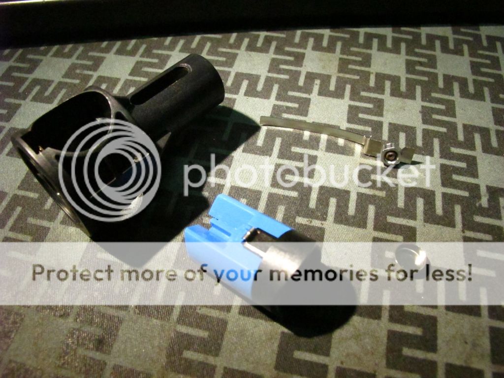
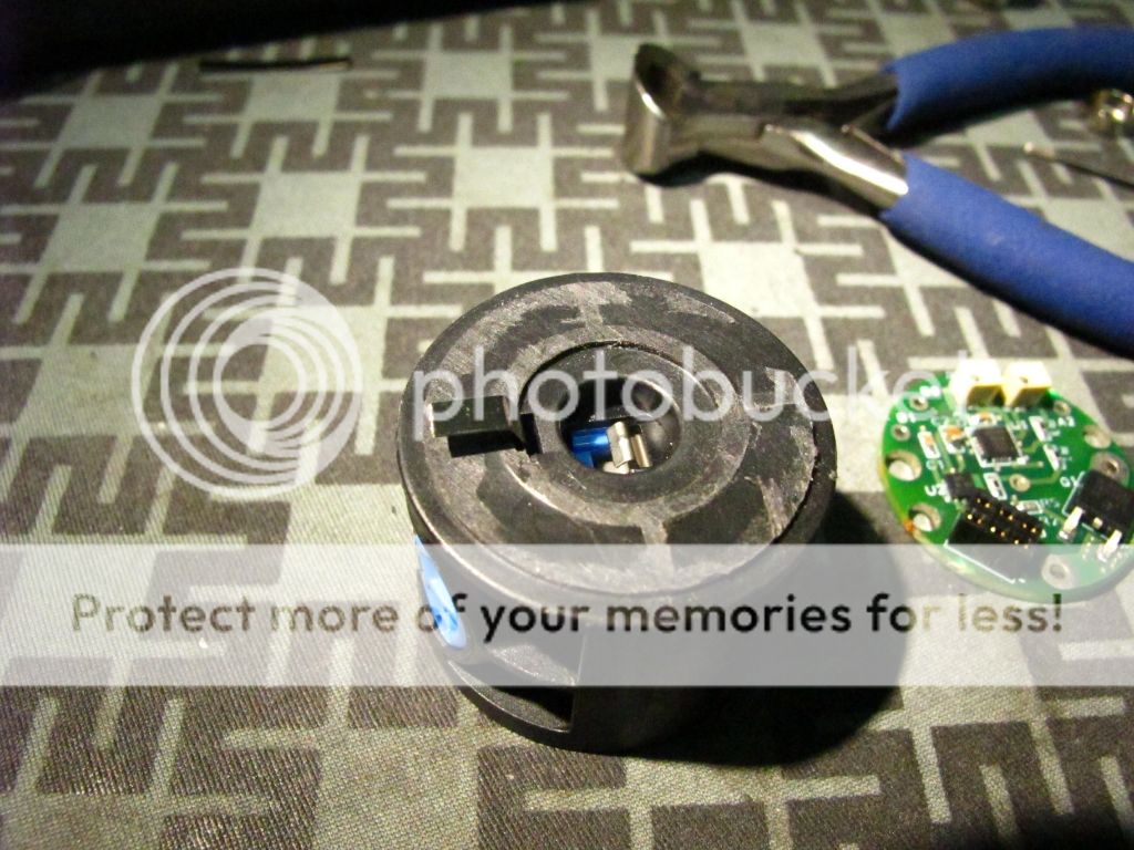
Seen here are the usual suspects. Pretty standard at this point.
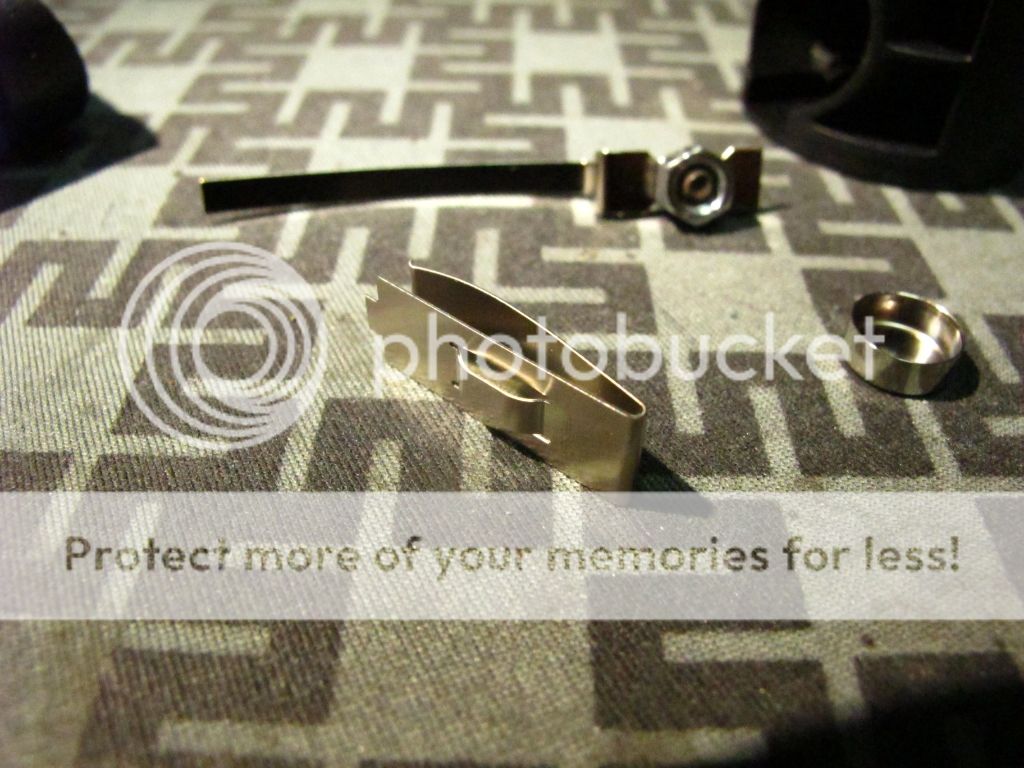
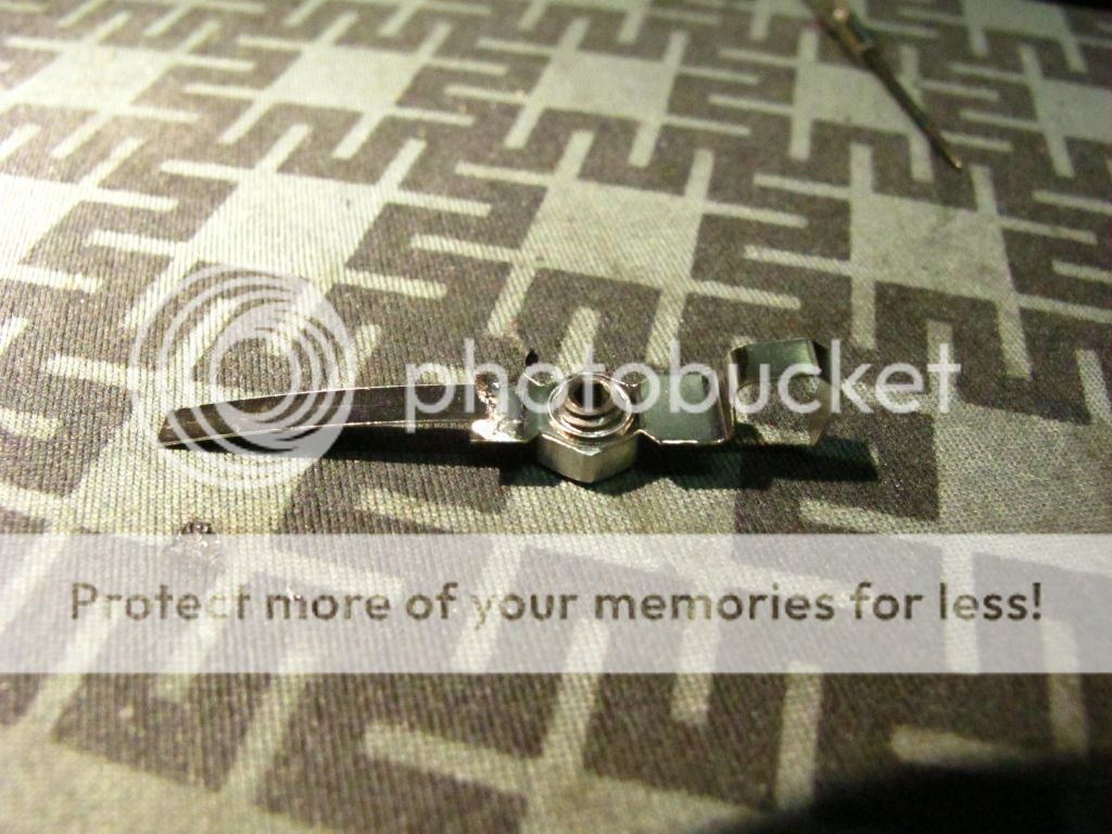
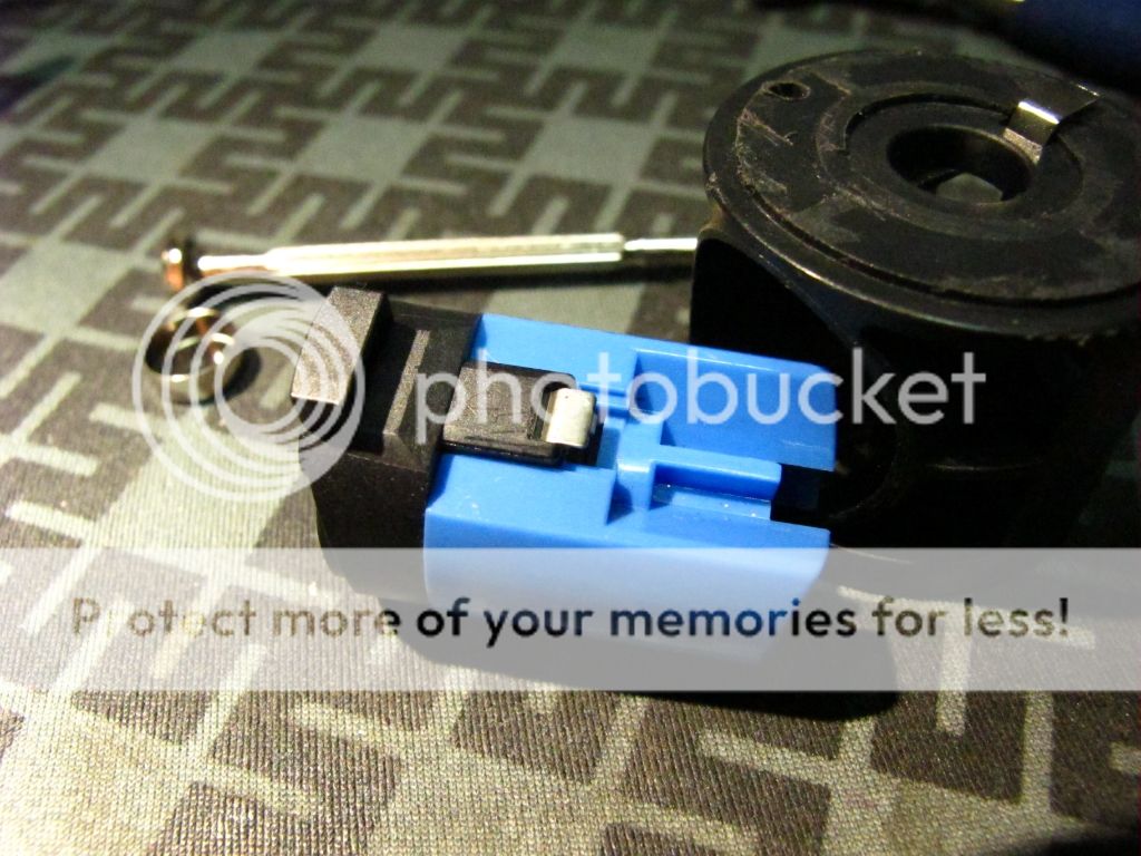
Here is the wild card, a completely different Positive battery contact design.
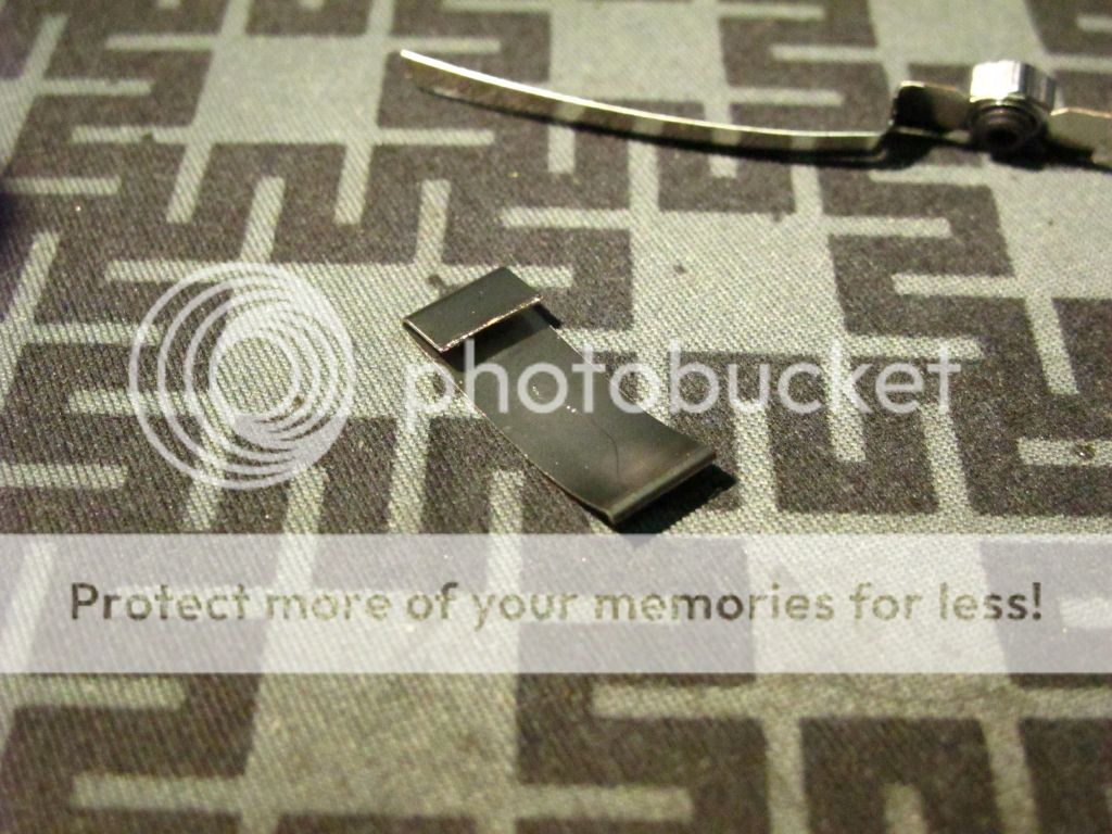
We start off by cutting it like this. The top part hides under the plastic lip of the channel it fits into. You want to cut it back just enough that the top part is not exposed when installed back into the switch tower.
Naturally, like before you have to cut off the bulb post and file things flat.
Your Negative tower strip gets trimmed and bent back like so.
Holes will get drilled that line up with holes in the regulator board. We will use these to pass wires.
Only one of these actually has to line up with a passthru' hole, but we'll keep it symmetrical.
These holes will drill thru' the top and also down thru' the middle support.
We will also need holes on the bottom. They cannot line up perfectly with the top holes due to the shape of the switch cavity.
I founds these corners to be the most ideal location.
I made some channels to expose metal of the battery contact like so.
This was done with a dremel using a milling bit.
You will remove the battery contact before doing this, of course.
The spare bit of negative strip get soldered onto the other end of this familiar part.
And then carefully bent inward to contact the bottom of the switch.
This will feed negative to the switch needed to control the regulator.
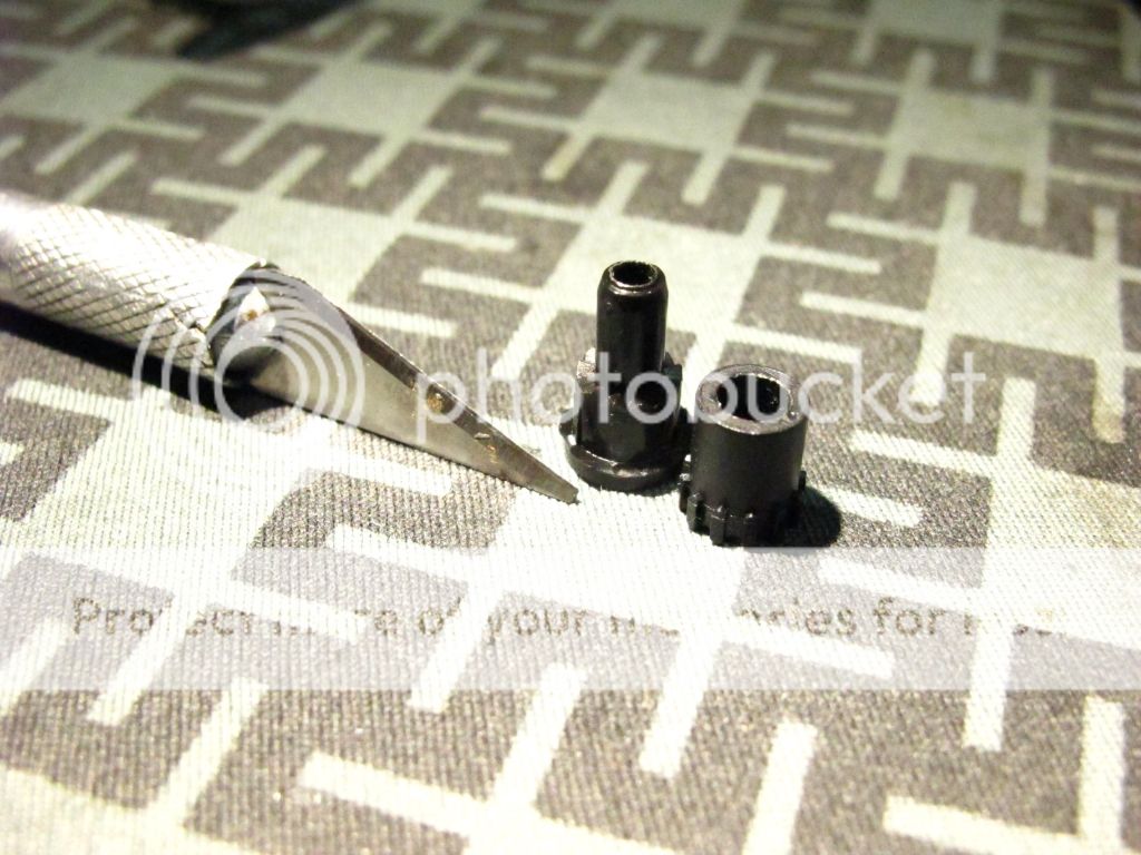
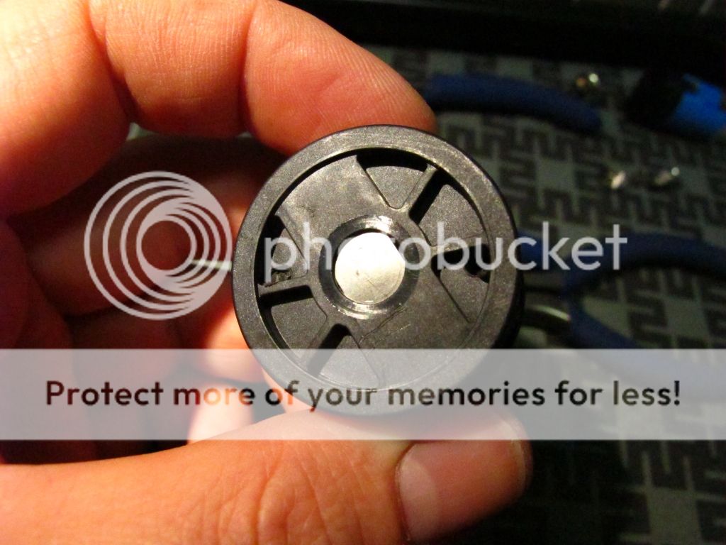
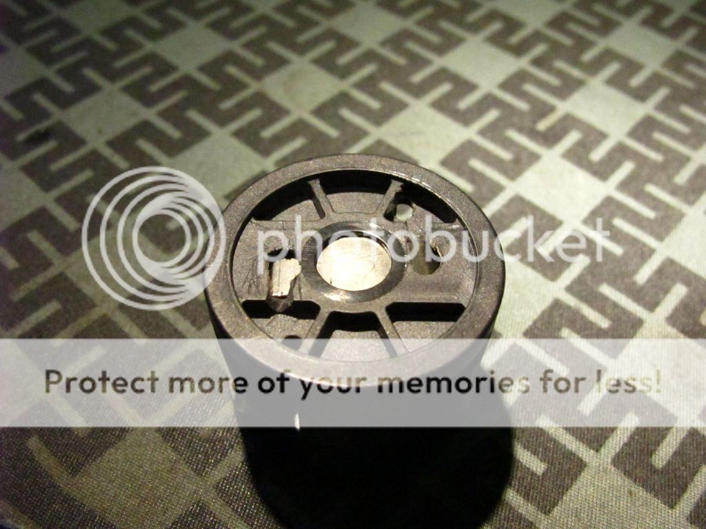
Talking about the switch, you need to pull it apart and cut off the ribs on the middle plastic piece to convert it to momentary function.
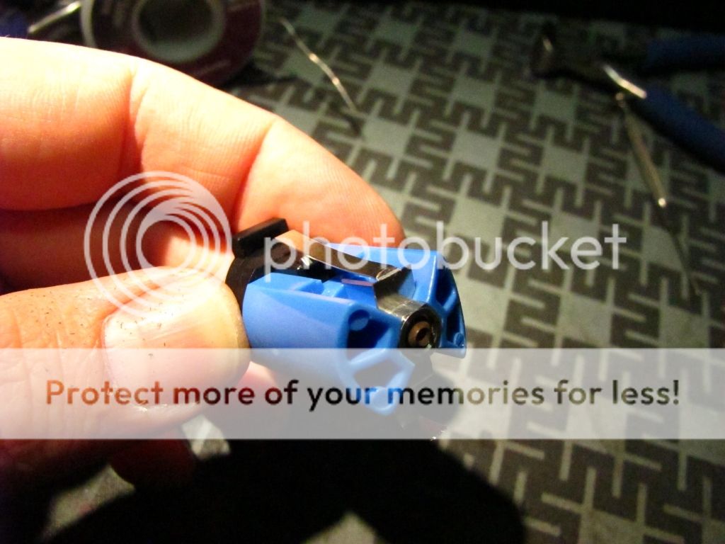
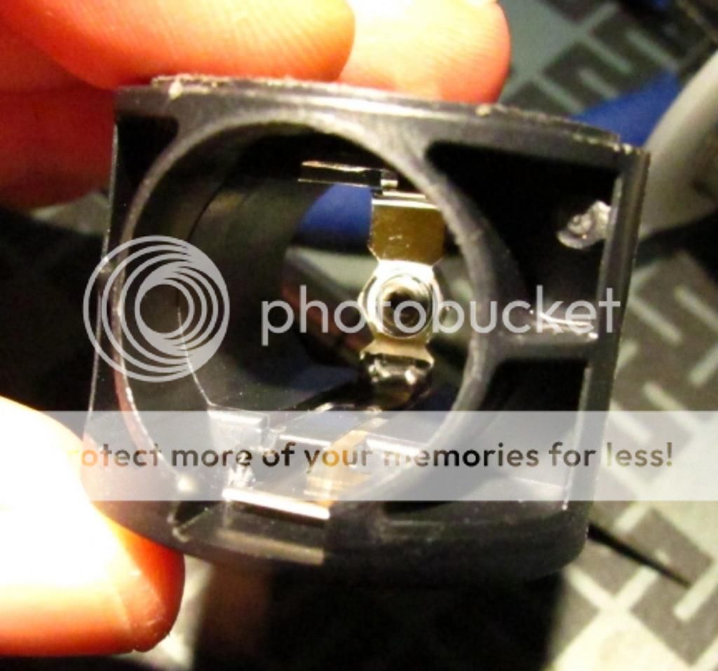
When you put the switch back together, take the bottom contact piece and flip it around, so the flat piece that is normally inside is now on the outside.
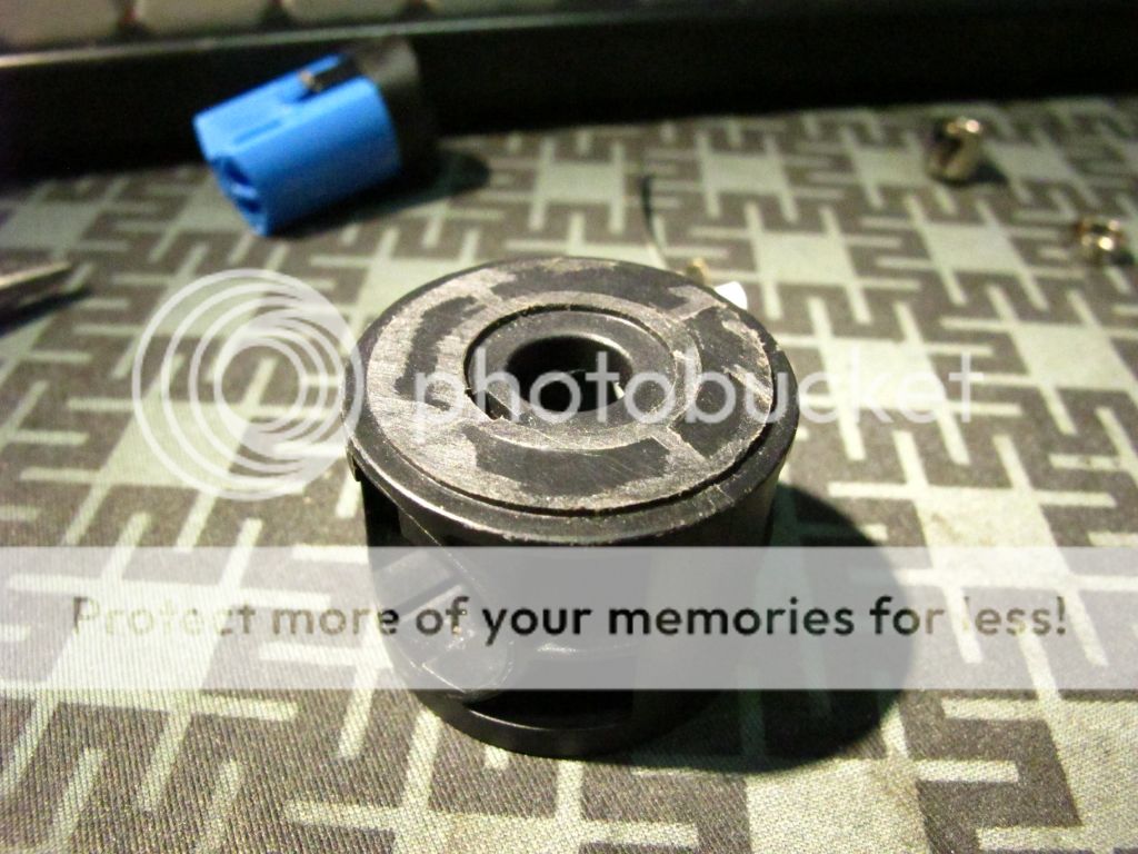
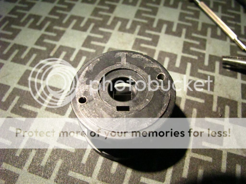
The bottom of the switch will now look like this.
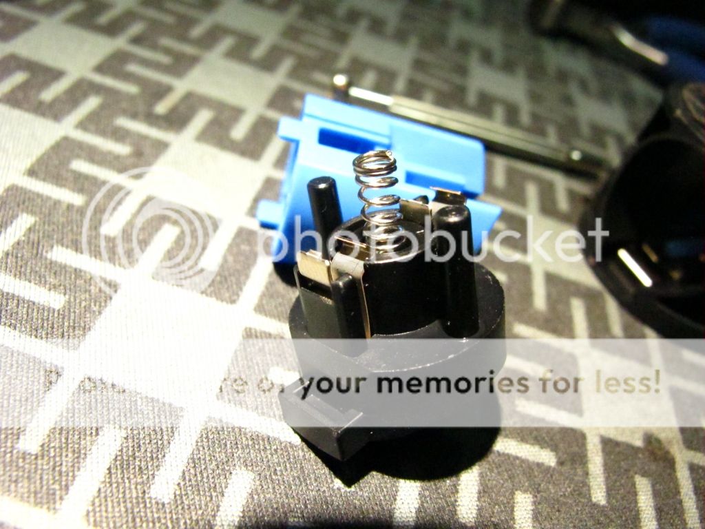
The top contact piece in the switch will remain the same.
See, the idea is with the top of the battery contact cut off, it will no longer touch the bottom of the switch, and there is enough room that the new negative contact strip can mate with the switch without touching the positive battery contact.
With the switch terminal in the stock position, it will push the negative strip down, and touch the battery contact.
With the switch terminal reversed and now flat, it will not longer put the strip down and this method can safely be used.
You might want to put some tape on top of the battery contact for good measure, unless . . .
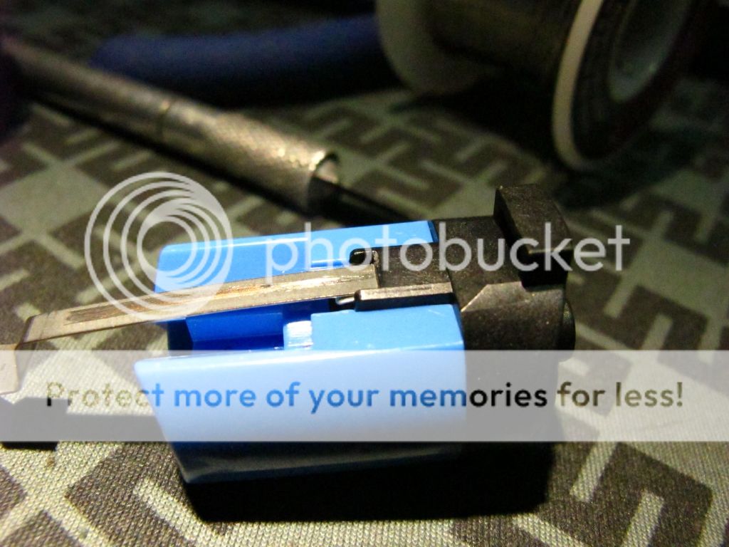
You are crafty enough to get the contact strip to slip INTO the switch as illustrated here with different strip.
The now flat contact allows us to do this, but it can be tricky to get the strip slipped into the switch like this when you are installing the switch back into the tower.
I was able to do it with a tiny screwdriver, and now the strip is securely supported above the battery contact in such a way that makes it impossible for them to touch and you are not dependent on insulating tape.
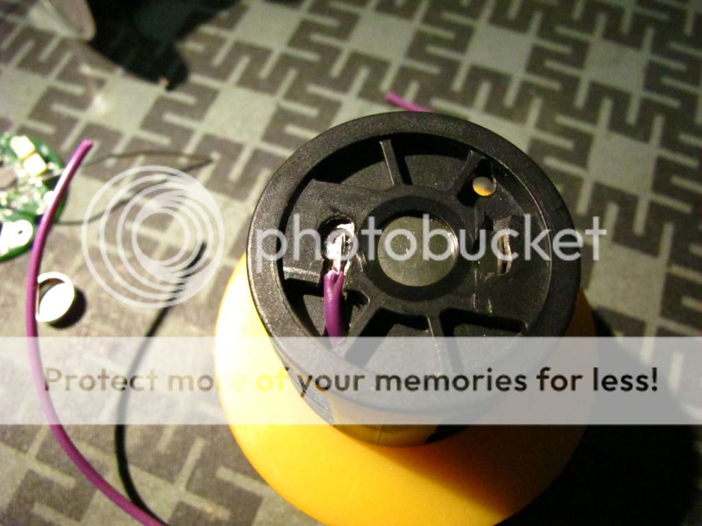
Back on top we feed the Positive wire that will supply the regulator with power.
It was intentionally made this long. You'll see why.
On the bottom, we connect the other side of said wire like so.
I chose the outer end of the battery contact for this.
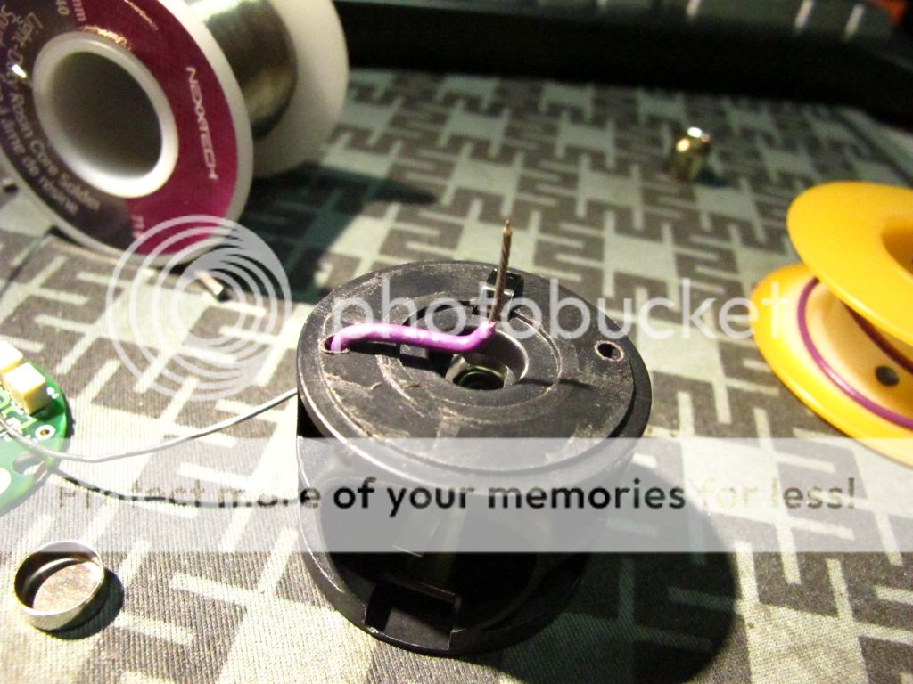
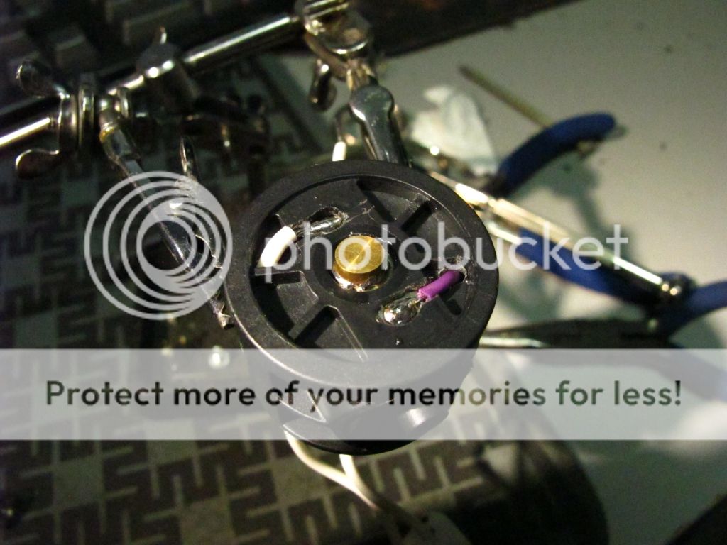
Back on top we solder wire to the spring cup to serve the control signal to the regulator.
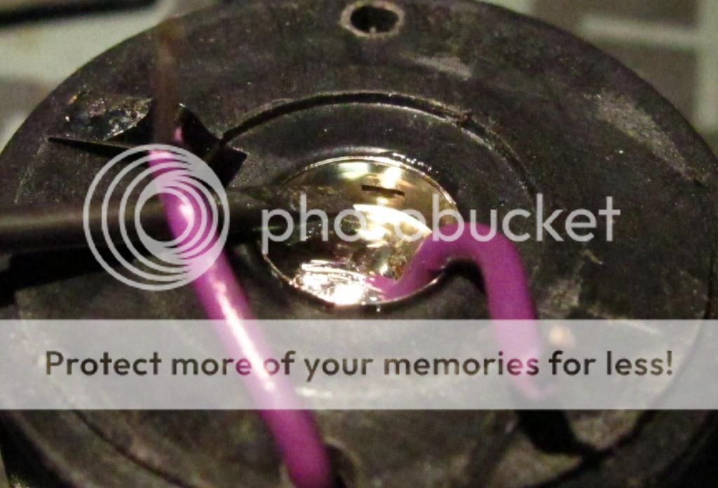
I put a couple careful dabs of glue, but the real trick is to take a small screwdriver and hammer, and peen/punch the inner sides of the spring cup to permanently fasten it into place. It's not going anywhere.
Pro tip: Don't use hot glue.
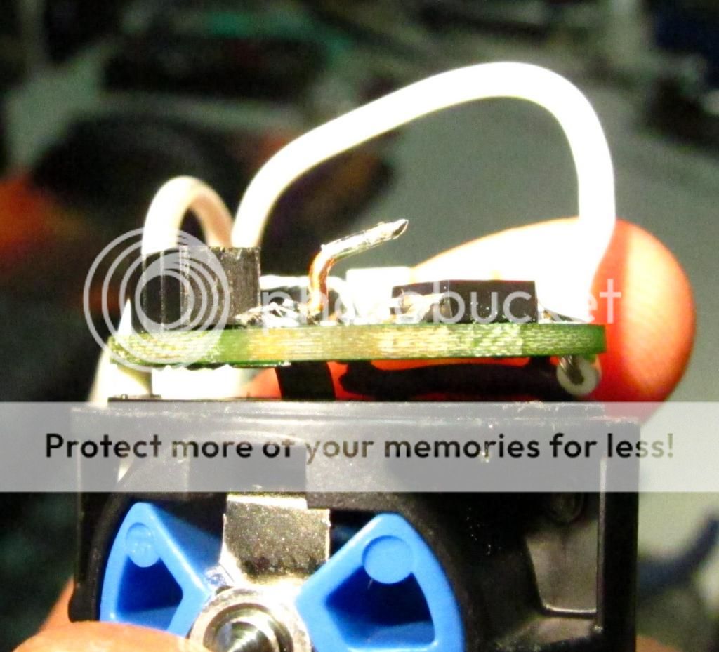
If you haven't figured it out already, this build maintains the ability to remove the switch at any time for servicing.
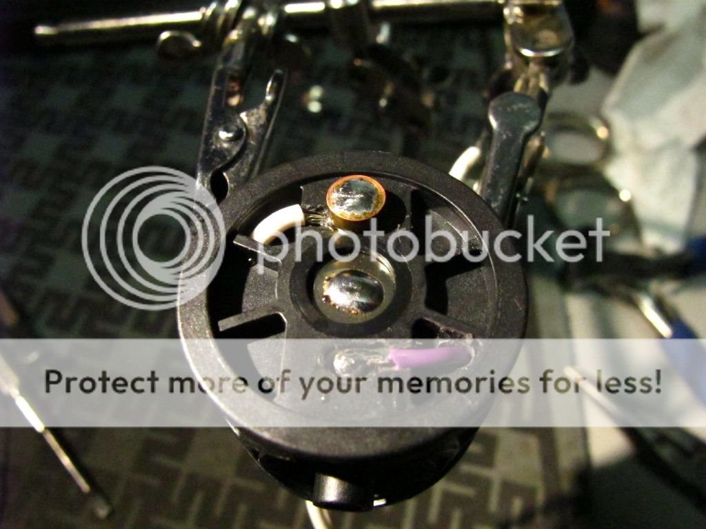
Seen here, I tinned a 6x2mm copper pill/slug I got from Int-Outdoor store, and the battery contact.
You're going to need something like this if you hope to use flat top cells.
The slug is now "flowed" into place.
Basically, I cleaned my solder tip and pressed it down on top of the slug until the solder tinned surfaces fused together.
It's a tricky move. You need to have the switch frame secured, with the iron in one hand and a small screwdriver in the other to guide/align the slug as necessary.
You will also note I have made the first connection of the bulb socket to the other end of the battery contact.
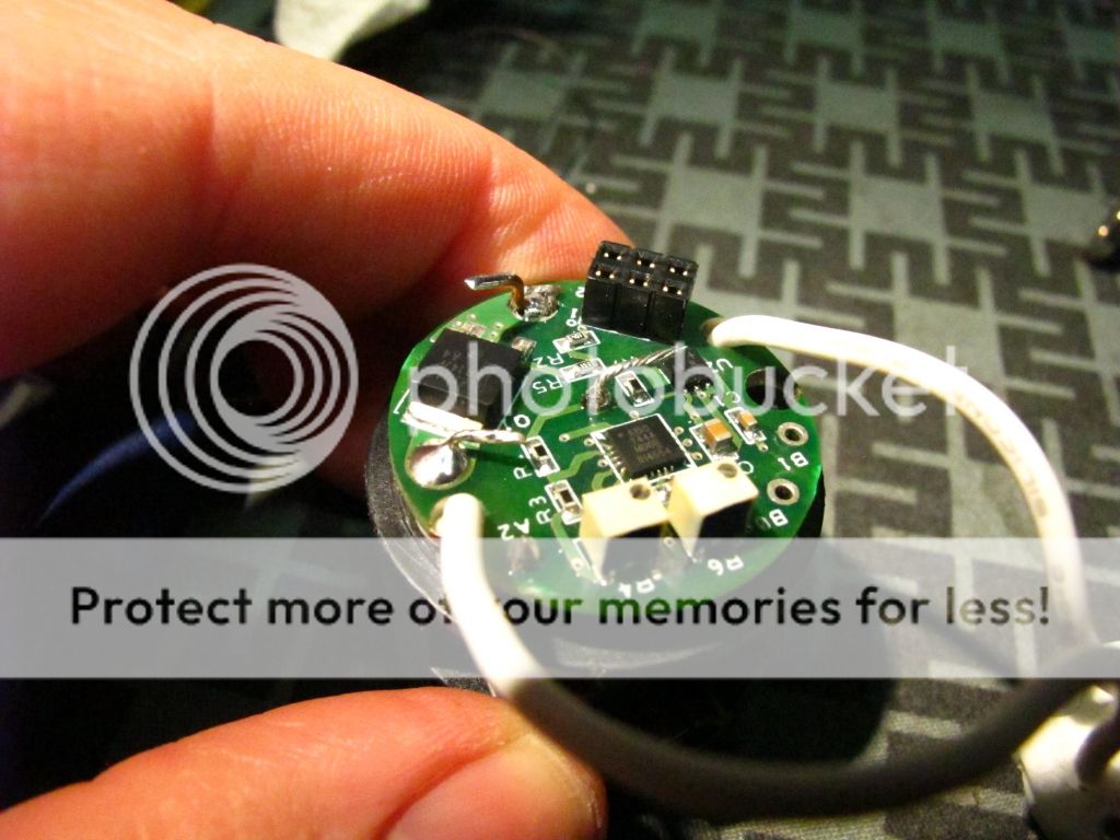
Seen here is the next connection of the bulb socket to the output of the regulator.
The wire gets fed down thru' the adjacent hole and up thru' the solder point.
This is for good reason which you'll see later.
The positive supply wire and control wire are soldered around this times also.
It's hard to see, but the negative supply strip gets soldered to the regulator input.
Basically, you tin the negative strip, and tin the regulators input contact on its both sides to the solder flows right thru' to both sides the hole, then carefully line them up, and fuse them together from the top.
I've added a piece of copper wire to the top if the input, again, for reasons explained next.
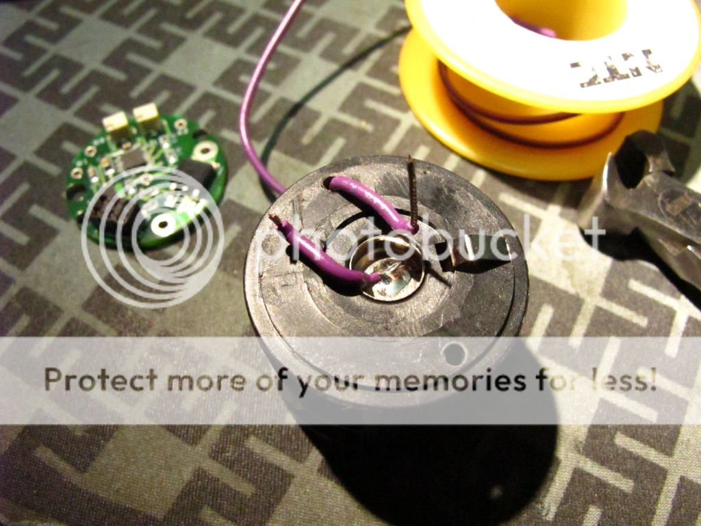
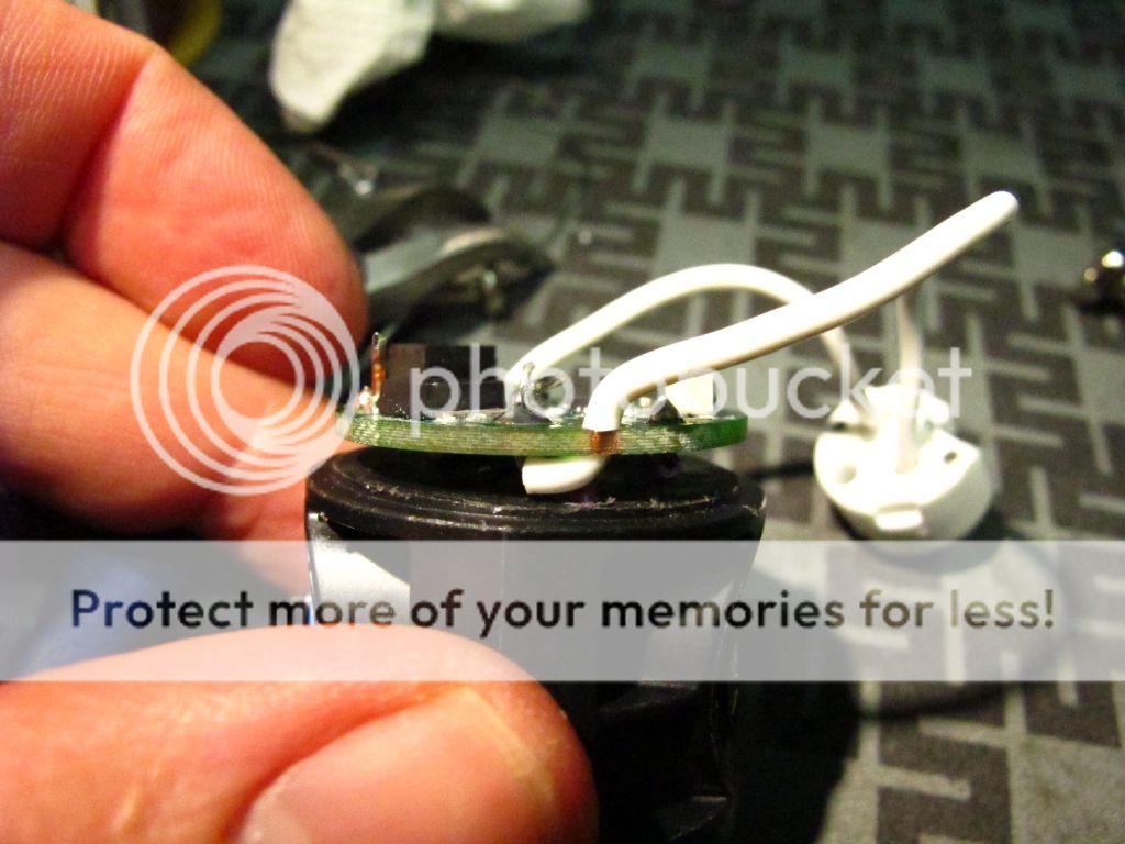
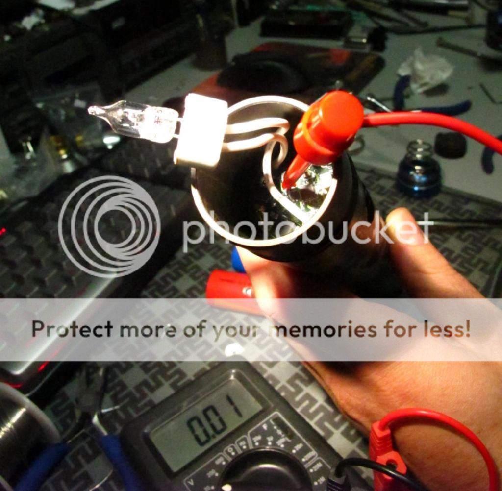
Test Points !
Can you imagine how much a pain it would be to calibrate this things if you did not make provisions to connect your multi meter ?
The positive wire, intentionally cut long,
The bulb socket wire fed down then back up,
And finally a piece of copper wire added to the top of the negative input all serve to give you something to hook your meter onto.
The centre point is common positive.
The Copper wire tests VBatt.
The bulb socket wire up tests the Vbulb.
When orienting your test points, bare in mind what is around or under them in case you slip connecting your meter.
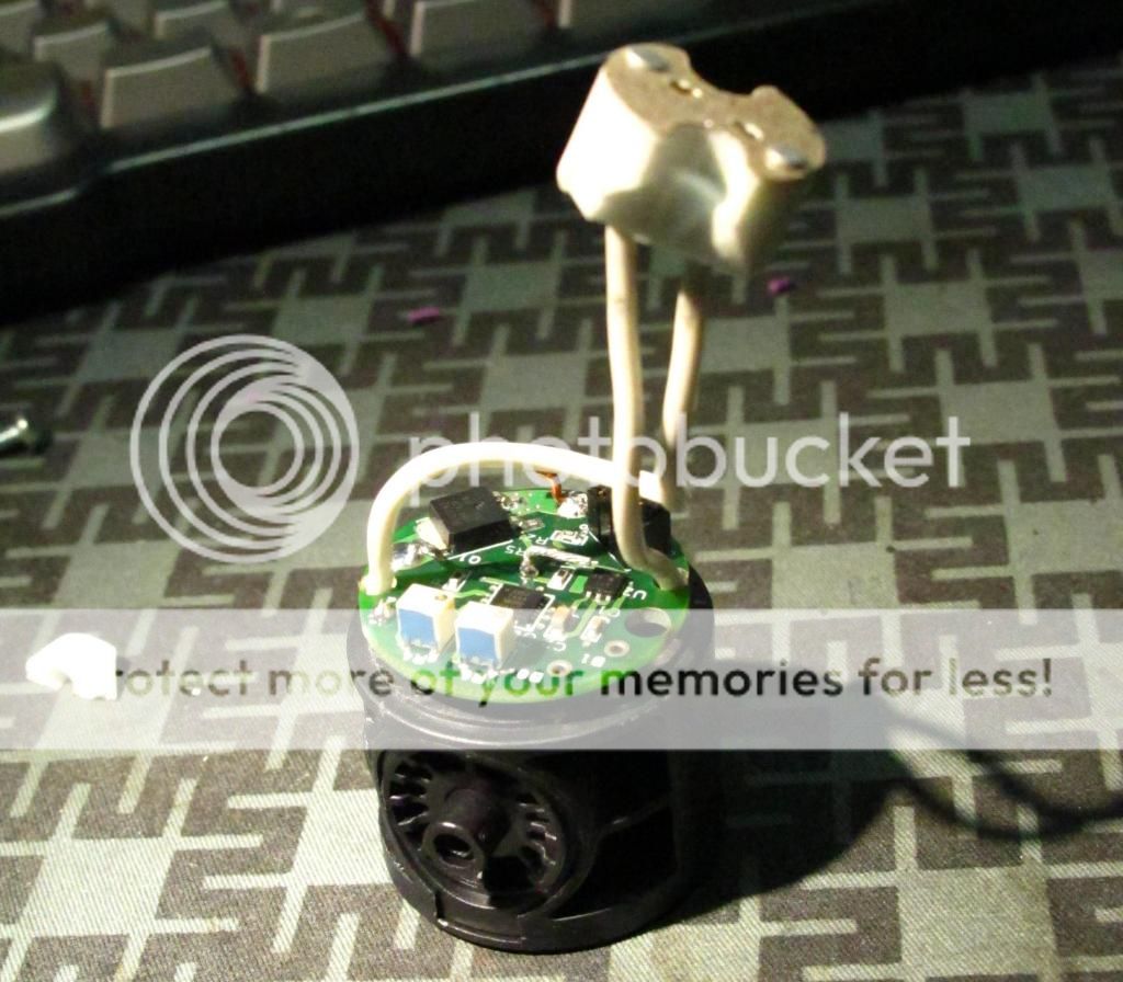
And finally, you're pretty much done.
Your new regulated m*g switch is ready for testing and installation.
You'll notice the socket is currently removed from it's base.
Removing the socket from the base is the easiest way to instal the switch assembly.
It also give you the ability to reprogram or recalibrate the regulator without having to remove and disassemble it like with the Kiu Socket.
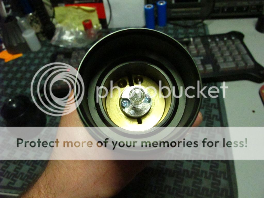
The complete installation.
You slip the socket wires in the channel on the base and screw the socket in place.
Be careful not to over tighten the socket as it's seat in the base it not perfectly flat and you will crack your socket.
In my sample, there was a slight upward towards centre taper in the socket seat for some reason.
Other then that, I find this Fivemega unit superior to the Kiu as you can adjust the height on the fly, do not need to remove the ring to install it, and can get it right out of the way to service the regulator. Also, copper is cool.
Now I know what some of you are thinking, how did I get the tower assembly out in the first place without the use of a special torx tool.
Well, that's easy . . . if you have the right materials.
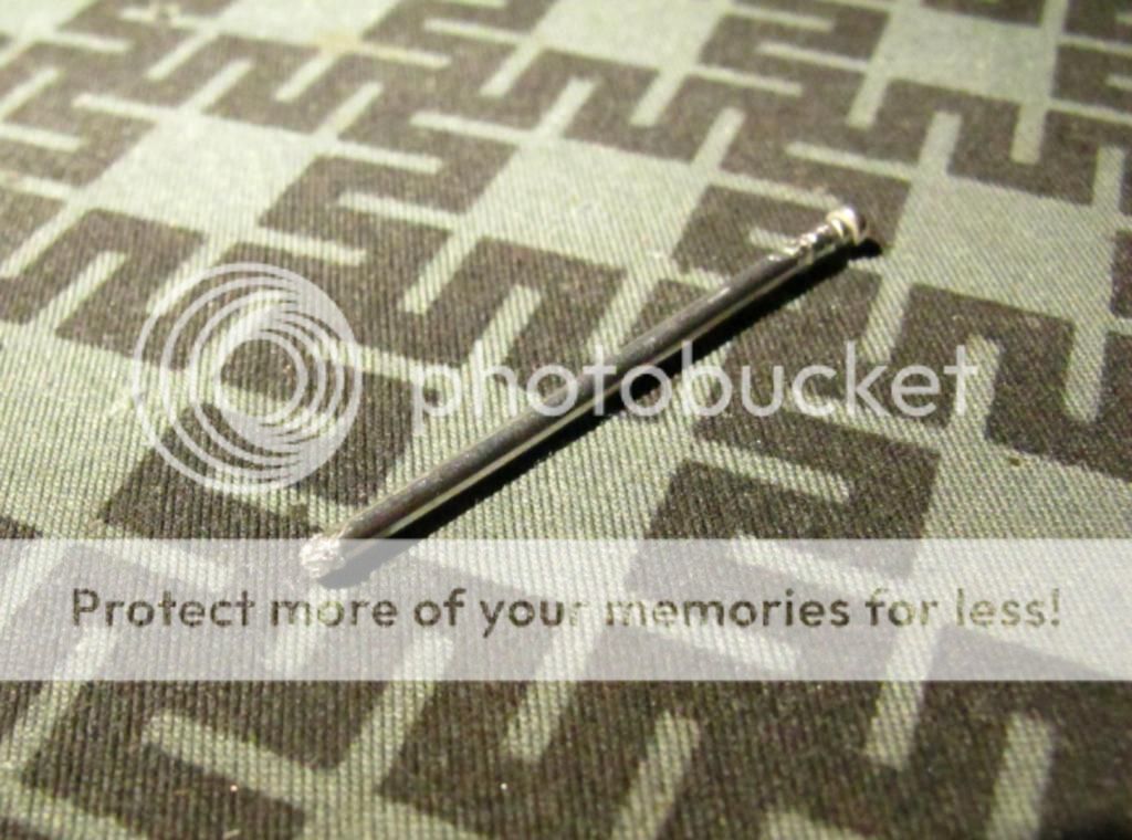
Seen here is a little piece of aluminum rod, is actually the shaft from a a common pop rivet.
3/8 rivet I think. This rod is 1.92mm (0.0755") wide.
It trimmed the point off the end, then hammered it flat, almost like a slot screwdriver.
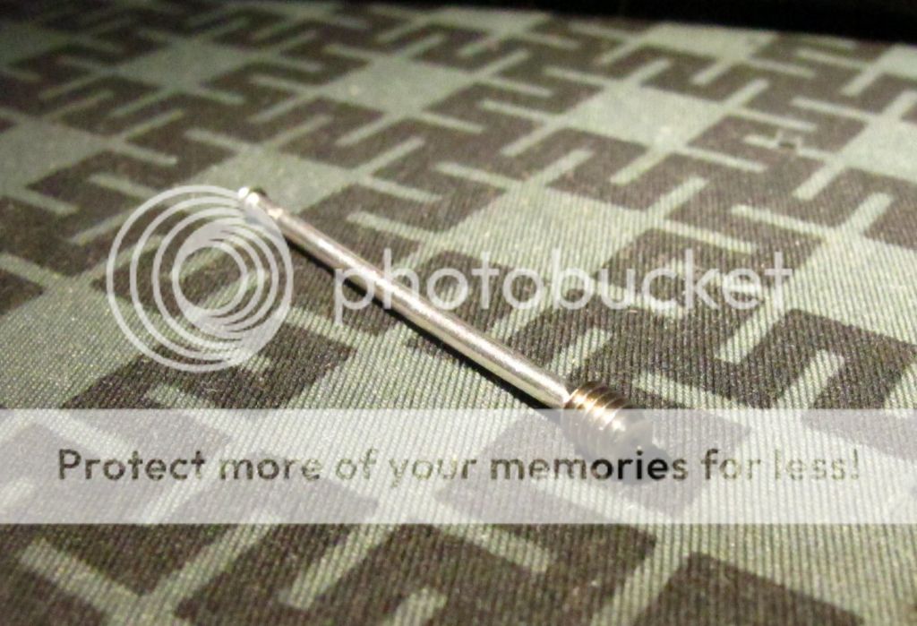
Then I put it into the switch hole until it met the swine torx screw, then used a hammer to swage the soft aluminum into the screw.
Once in, I grabbed the rod with a small vise grip and spun the screw loose.
I was then free to get a replacement screw with the standard allen key size.
Once you've build one of these regulator switches, you can pretty much run most any of the famous hotwire bulbs off whatever batteries you can physically fit into your host. Assuming of course, you can fit enough power to run whatever bulb.
The JM-PH-D1 has been out a while now, there are instructions available that show you how to build a regulated mag switch using the old style M*g tower, with the Kiu socket, and using, I want to say, less efficient and more invasive techniques.
Submitted here are updated instructions using the new style T8 m*g tower switch assemblies, the ingenious Fivemega G6.35 socket, and my personal flavor of assembly methods.
Seen here are the usual suspects. Pretty standard at this point.
Here is the wild card, a completely different Positive battery contact design.
We start off by cutting it like this. The top part hides under the plastic lip of the channel it fits into. You want to cut it back just enough that the top part is not exposed when installed back into the switch tower.
Naturally, like before you have to cut off the bulb post and file things flat.
Your Negative tower strip gets trimmed and bent back like so.
Holes will get drilled that line up with holes in the regulator board. We will use these to pass wires.
Only one of these actually has to line up with a passthru' hole, but we'll keep it symmetrical.
These holes will drill thru' the top and also down thru' the middle support.
We will also need holes on the bottom. They cannot line up perfectly with the top holes due to the shape of the switch cavity.
I founds these corners to be the most ideal location.
I made some channels to expose metal of the battery contact like so.
This was done with a dremel using a milling bit.
You will remove the battery contact before doing this, of course.
The spare bit of negative strip get soldered onto the other end of this familiar part.
And then carefully bent inward to contact the bottom of the switch.
This will feed negative to the switch needed to control the regulator.
Talking about the switch, you need to pull it apart and cut off the ribs on the middle plastic piece to convert it to momentary function.
When you put the switch back together, take the bottom contact piece and flip it around, so the flat piece that is normally inside is now on the outside.
The bottom of the switch will now look like this.
The top contact piece in the switch will remain the same.
See, the idea is with the top of the battery contact cut off, it will no longer touch the bottom of the switch, and there is enough room that the new negative contact strip can mate with the switch without touching the positive battery contact.
With the switch terminal in the stock position, it will push the negative strip down, and touch the battery contact.
With the switch terminal reversed and now flat, it will not longer put the strip down and this method can safely be used.
You might want to put some tape on top of the battery contact for good measure, unless . . .
You are crafty enough to get the contact strip to slip INTO the switch as illustrated here with different strip.
The now flat contact allows us to do this, but it can be tricky to get the strip slipped into the switch like this when you are installing the switch back into the tower.
I was able to do it with a tiny screwdriver, and now the strip is securely supported above the battery contact in such a way that makes it impossible for them to touch and you are not dependent on insulating tape.
Back on top we feed the Positive wire that will supply the regulator with power.
It was intentionally made this long. You'll see why.
On the bottom, we connect the other side of said wire like so.
I chose the outer end of the battery contact for this.
Back on top we solder wire to the spring cup to serve the control signal to the regulator.
I put a couple careful dabs of glue, but the real trick is to take a small screwdriver and hammer, and peen/punch the inner sides of the spring cup to permanently fasten it into place. It's not going anywhere.
Pro tip: Don't use hot glue.
If you haven't figured it out already, this build maintains the ability to remove the switch at any time for servicing.
Seen here, I tinned a 6x2mm copper pill/slug I got from Int-Outdoor store, and the battery contact.
You're going to need something like this if you hope to use flat top cells.
The slug is now "flowed" into place.
Basically, I cleaned my solder tip and pressed it down on top of the slug until the solder tinned surfaces fused together.
It's a tricky move. You need to have the switch frame secured, with the iron in one hand and a small screwdriver in the other to guide/align the slug as necessary.
You will also note I have made the first connection of the bulb socket to the other end of the battery contact.
Seen here is the next connection of the bulb socket to the output of the regulator.
The wire gets fed down thru' the adjacent hole and up thru' the solder point.
This is for good reason which you'll see later.
The positive supply wire and control wire are soldered around this times also.
It's hard to see, but the negative supply strip gets soldered to the regulator input.
Basically, you tin the negative strip, and tin the regulators input contact on its both sides to the solder flows right thru' to both sides the hole, then carefully line them up, and fuse them together from the top.
I've added a piece of copper wire to the top if the input, again, for reasons explained next.
Test Points !
Can you imagine how much a pain it would be to calibrate this things if you did not make provisions to connect your multi meter ?
The positive wire, intentionally cut long,
The bulb socket wire fed down then back up,
And finally a piece of copper wire added to the top of the negative input all serve to give you something to hook your meter onto.
The centre point is common positive.
The Copper wire tests VBatt.
The bulb socket wire up tests the Vbulb.
When orienting your test points, bare in mind what is around or under them in case you slip connecting your meter.
And finally, you're pretty much done.
Your new regulated m*g switch is ready for testing and installation.
You'll notice the socket is currently removed from it's base.
Removing the socket from the base is the easiest way to instal the switch assembly.
It also give you the ability to reprogram or recalibrate the regulator without having to remove and disassemble it like with the Kiu Socket.
The complete installation.
You slip the socket wires in the channel on the base and screw the socket in place.
Be careful not to over tighten the socket as it's seat in the base it not perfectly flat and you will crack your socket.
In my sample, there was a slight upward towards centre taper in the socket seat for some reason.
Other then that, I find this Fivemega unit superior to the Kiu as you can adjust the height on the fly, do not need to remove the ring to install it, and can get it right out of the way to service the regulator. Also, copper is cool.
Now I know what some of you are thinking, how did I get the tower assembly out in the first place without the use of a special torx tool.
Well, that's easy . . . if you have the right materials.
Seen here is a little piece of aluminum rod, is actually the shaft from a a common pop rivet.
3/8 rivet I think. This rod is 1.92mm (0.0755") wide.
It trimmed the point off the end, then hammered it flat, almost like a slot screwdriver.
Then I put it into the switch hole until it met the swine torx screw, then used a hammer to swage the soft aluminum into the screw.
Once in, I grabbed the rod with a small vise grip and spun the screw loose.
I was then free to get a replacement screw with the standard allen key size.
Last edited: