
DIWdiver
Flashlight Enthusiast
Edited 1/11/15
Yes, that's right, 25 amp adjustable driver, two modes. I'm looking to see if there's enough interest in one to make it worth building. Please let me know what you think.
$35 USD would get you all this:
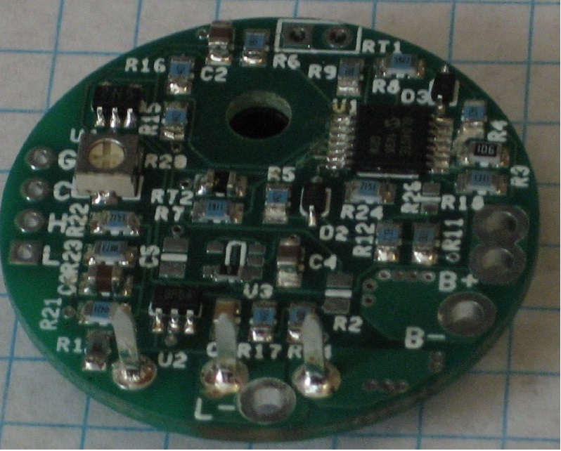
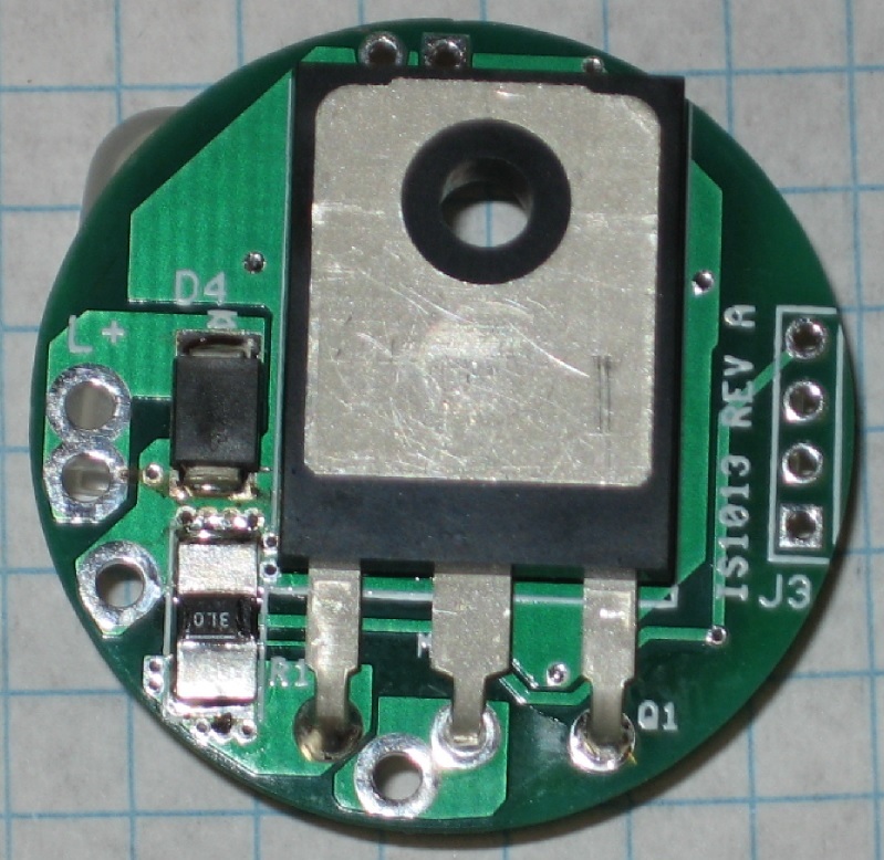
It would be based on my existing IS1011 automotive driver discussed extensively here: http://www.candlepowerforums.com/vb...Automotive-linear-13-5A-LED-driver-adjustable. It would be the same size and configuration. Someone asked me if I could mod one to 21A. I figured with a new board, I could go as high as 25A.
Edit: it would be 33mm round to fit MAG-D tube.
This would probably be offered in several versions:
One cell, input voltage 3.0-5.0V
Two-cell, input voltage 5.0-9.0V
Multi-cell, input voltage 8-35V (not sure this one makes sense, as there are other options in this range).
Edit: two versions: 3.0-5.5V, 3.5-36V.
Each version would be offered in several current ratings up to 25A. There is an onboard potentiometer that can be used to adjust the outut from zero to whatever the rating is for that particular driver.
The driver would have two modes, high (100%) and low (25%). Any adjustment to the potentiometer adjusts both high and low proportinally, so that low is always 25% of high. The 4:1 ratio can be customized upon request. The switch required to run the modes is a double throw type, so a 'clicky' type switch will not work. Something like this is needed: http://www.digikey.com/product-detail/en/100SP3T1B1M1REH/EG2376-ND/378845. With a 'clicky' type switch you could control only one of the modes, i.e. high and off or low and off. For best results I recommend switches with gold plated contacts, like the one in the link.
The driver would draw about 10 mA even when switched off. This could be a problem in a flashlight that sits idle for long periods. An alternate wiring scheme can reduce this to a few microamps using a double-pole switch like this: http://www.digikey.com/product-detail/en/M2023SS1G01/M2023SS1G01-ND/1027302 instead of the single pole switch mentioned above.
Edit: 2-3 mA normal, less than 1 mA in undervoltage cutout mode.
Like the IS1011, it would have an on-board temperature sensor to protect the driver from overheating. In order for this to work properly, the driver must be properly mounted to an aluminum or copper heatsink. There would also be a point to connect an external thermistor for protecting the LED(s) if they are on a different heatsink.
Instead of the over-voltage cutout of the IS1011, this would have an undervoltage cutout, probably at 2.7V for the single-cell version, 5.4V for the two-cell version, and disabled for the multi-cell. This could be disabled for those who would rather sacrifice the battery to keep the light running.
If it's of interest, I might set it up so the external thermistor input could also be used for a PWM input instead. PWM frequencies could be up to 20 kHz (higher on request). However, the PWM signal would be filtered in the driver to provide an analog dimming function to the LED. This is better for some digital cameras, though it can cause some tint shift in the LED. If it were desired to apply PWM to the LED, this could be accomodated. I'd have to investigate how high a frequency is practical. I'm guessing 10 kHz-ish.
Sound too good to be true?
***HERE'S THE CATCH***
The driver would be a linear driver. This means that the output voltage cannot be higher than the input voltage, and to have decent efficiency, the input voltage needs to be close to the output voltage. This limits what battery/led combinations would work well. For the single-cell driver you'd use a single cell (or several in parallel), and a single LED (or several in parallel). For the two-cell driver you'd use, obviously, two cells in series and two LEDs in series (or parallel combinations thereof).
With these combinations, the efficiency can actually be quite good. With a 3.5V LED and a 4.0V battery (LiIon batteries won't stay above 4.0V under load except perhaps very briefly), you'd get 87% efficiency. As the battery voltage falls to 3.65V, the efficiency would rise to 96%. As the voltage continues to drop, the regulator would begin to "drop out", meaning the output voltage would begin to fall. All LEDs have a voltage vs. current curve, and as the voltage falls the current drops according to the LED's curve. The efficiency would remain near 94-96% as the input voltage drops to 3.0V. After this the dropout voltage begins to increase and the efficiency begins to fall. Operation in this region (below 3.0V input) would not be guaranteed.
If your LED voltage were 2.95V, the driver would remain in regulation until the battery voltage reached 3.1V, and the efficiency would start at 74% and climb gradually to 95%.
The 'dropout voltage' of a driver is the minimum input-output voltage differential required to maintain regulated current. This is a characteristic of all linear and buck type regulators. The 0.15V dropout voltage of this driver at 25A would be considered quite low. At lower currents, the dropout voltage is even lower.
Cheers.
D
Yes, that's right, 25 amp adjustable driver, two modes. I'm looking to see if there's enough interest in one to make it worth building. Please let me know what you think.
$35 USD would get you all this:
It would be based on my existing IS1011 automotive driver discussed extensively here: http://www.candlepowerforums.com/vb...Automotive-linear-13-5A-LED-driver-adjustable. It would be the same size and configuration. Someone asked me if I could mod one to 21A. I figured with a new board, I could go as high as 25A.
Edit: it would be 33mm round to fit MAG-D tube.
This would probably be offered in several versions:
One cell, input voltage 3.0-5.0V
Two-cell, input voltage 5.0-9.0V
Multi-cell, input voltage 8-35V (not sure this one makes sense, as there are other options in this range).
Edit: two versions: 3.0-5.5V, 3.5-36V.
Each version would be offered in several current ratings up to 25A. There is an onboard potentiometer that can be used to adjust the outut from zero to whatever the rating is for that particular driver.
The driver would have two modes, high (100%) and low (25%). Any adjustment to the potentiometer adjusts both high and low proportinally, so that low is always 25% of high. The 4:1 ratio can be customized upon request. The switch required to run the modes is a double throw type, so a 'clicky' type switch will not work. Something like this is needed: http://www.digikey.com/product-detail/en/100SP3T1B1M1REH/EG2376-ND/378845. With a 'clicky' type switch you could control only one of the modes, i.e. high and off or low and off. For best results I recommend switches with gold plated contacts, like the one in the link.
The driver would draw about 10 mA even when switched off. This could be a problem in a flashlight that sits idle for long periods. An alternate wiring scheme can reduce this to a few microamps using a double-pole switch like this: http://www.digikey.com/product-detail/en/M2023SS1G01/M2023SS1G01-ND/1027302 instead of the single pole switch mentioned above.
Edit: 2-3 mA normal, less than 1 mA in undervoltage cutout mode.
Like the IS1011, it would have an on-board temperature sensor to protect the driver from overheating. In order for this to work properly, the driver must be properly mounted to an aluminum or copper heatsink. There would also be a point to connect an external thermistor for protecting the LED(s) if they are on a different heatsink.
Instead of the over-voltage cutout of the IS1011, this would have an undervoltage cutout, probably at 2.7V for the single-cell version, 5.4V for the two-cell version, and disabled for the multi-cell. This could be disabled for those who would rather sacrifice the battery to keep the light running.
If it's of interest, I might set it up so the external thermistor input could also be used for a PWM input instead. PWM frequencies could be up to 20 kHz (higher on request). However, the PWM signal would be filtered in the driver to provide an analog dimming function to the LED. This is better for some digital cameras, though it can cause some tint shift in the LED. If it were desired to apply PWM to the LED, this could be accomodated. I'd have to investigate how high a frequency is practical. I'm guessing 10 kHz-ish.
Sound too good to be true?
***HERE'S THE CATCH***
The driver would be a linear driver. This means that the output voltage cannot be higher than the input voltage, and to have decent efficiency, the input voltage needs to be close to the output voltage. This limits what battery/led combinations would work well. For the single-cell driver you'd use a single cell (or several in parallel), and a single LED (or several in parallel). For the two-cell driver you'd use, obviously, two cells in series and two LEDs in series (or parallel combinations thereof).
With these combinations, the efficiency can actually be quite good. With a 3.5V LED and a 4.0V battery (LiIon batteries won't stay above 4.0V under load except perhaps very briefly), you'd get 87% efficiency. As the battery voltage falls to 3.65V, the efficiency would rise to 96%. As the voltage continues to drop, the regulator would begin to "drop out", meaning the output voltage would begin to fall. All LEDs have a voltage vs. current curve, and as the voltage falls the current drops according to the LED's curve. The efficiency would remain near 94-96% as the input voltage drops to 3.0V. After this the dropout voltage begins to increase and the efficiency begins to fall. Operation in this region (below 3.0V input) would not be guaranteed.
If your LED voltage were 2.95V, the driver would remain in regulation until the battery voltage reached 3.1V, and the efficiency would start at 74% and climb gradually to 95%.
The 'dropout voltage' of a driver is the minimum input-output voltage differential required to maintain regulated current. This is a characteristic of all linear and buck type regulators. The 0.15V dropout voltage of this driver at 25A would be considered quite low. At lower currents, the dropout voltage is even lower.
Cheers.
D
Last edited:
") ).
).