Gauss163 said:
Does anyone know precisely what the iCharger special modes do? It has two special modes, for DC motor breakin, and Foam cutting. Both allow one to set the current and voltage. How does it function in those two modes? Will either allow it to function as a bench power supply in either CC or CV mode?
Today i played with the 106B for a "vacuum" cleaner repair project and had the same question. The iCharger instruction manual doesn't document the modes very clearly. I tested the "Motor Drive Mode" on the little motor: after setting 7.20V voltage AND 10.0A amperage and pressing the <START>-button, the voltage and current started out at 0.00V 0.0A and slowly ramped up automatically in parallel. The voltage ramped up to 7.20V (bullseye!) WHILE the current didn't go further than 1.4A. Apparently this special mode seeems to emulate a so-called "constant voltage source" (as heard from our junior college texts:tinfoil
")
, and the 10.0A setting is only to protect your motor, limiting the power wattage (see the motor performance graphs in the PDF datasheet of the motor model). Of course, one doesn't need to connect a motor to this mode. One could connect any other electronic part/component/device which requires a
constant DC voltage source. Ohm's Law determines the current draw naturally. The Imax B6 instruction manual refers to their (apparently equivalent) special mode as "
DC/DC Converter" mode. Imho either manual should have mentioned the principle/concept/term "constant DC voltage source" to describe and explain what this special mode in essence is!
:fail:
The other iCharger special mode, called "Foam Cut Mode", must be emulating a
constant DC current source then yes. While Ohm's Law determines the required voltage naturally, one still needs to enter a voltage setting for protection of the connected part/component/device/circuit. Again, the manual should have mentioned this term in their explanation of the mode. In common electronics practice a constant current source is rarely needed afaik, rarely a useful thing to have (Imax B6 doesn't have it). Foam cutting with a hot wire is one of the few realistic practical examples of application: when the wire is still cold, the required voltage is less, and when the wire is constant hot, the required voltage settles at the elevated level. Unfortunately, i can't make any sense of the
operation of the mode or can you, which is a shame:
Since i by now know that my lil motor consumes ~1.35A when connected to 7.20V voltage, i could test this CC-mode on the motor as well: I'd set "
1.3A", press <START>, see the motor spinning up and then observe how the voltage changes until it settles to ~7.20V,
hopefully.
Should boil down to the same thing, same-same, because of Ohm's Law. I'll test it later today, stay tuna.
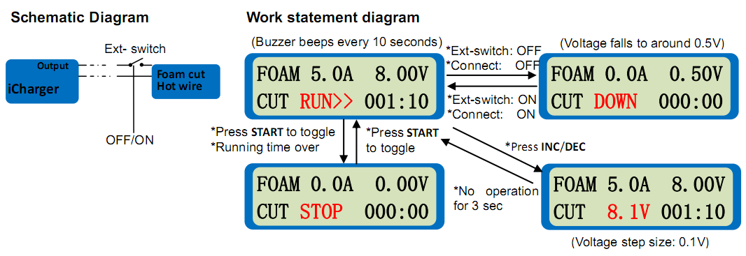
EDIT: I've tested it. Never mind the above schematic diagram for the user's operation of the mode. You simply long-press the <START>-button, then the device waits for 3sec before it ramps up current and voltage, again starting from zero. I also inserted my DMM in the circuitry to measure the current independently. Kinda interesting experience, i tested several times:
Note that i did not connect the leads directly to the motor but to the battery compartment. After i pressed the <START>-button, every time the current would indeed increase from zero to 1.3A eventually (bullseye!, as re-confirmed by the DMM), say within
2-6sec of ramping-up time. But the voltage (as displayed by the 106B) ramped up from zero to a
different stationary voltage level in each test during that time (
2-6sec). Sometimes that stationary voltage would be
0.74V,
0.83V,
1.07V,
8.11V, or
10.86V (i had set "
12.00V" for this CC-mode). So not surprisingly, only for tests which surpassed a voltage level of ~
1.3 Volts (combined with at least ~
0.9A, both "measured" at the battery compartment) did the motor start spinning, and then the voltage (and current) would automatically
continue to ramp up to
8.11V or
10.86V, either at 1.3A, of course. Could the motor also start spinning at the
0.74V, if the supplied current had been set higher than 1.3A? Maybe; the exact electrical threshold conditions (voltage vs. current) for getting the motor to finally start spinning are probably listed/graphed in the motor PDF datasheet (but that's offtopic). We are learning that, if you supply power to an electrical circuit
in form of a (ramping) constant DC current source, you will get unpredictable start-up behavior and unexpected results! Note that this special iCharger mode is
not an
ideal constant current source anyway, why?, because the device takes
at least 2sec or whatever to ramp up to the constant current level, and during that ramping-up time your circuit could fall into a different stationary state than desired/calculated, as witnessed with this vacuum cleaner motor example. Also note the
10.86V which is higher than what the battery compartment would usually supply (
7.2V nominal). If the voltage out of the 106B had shot up even higher, say 14V at the set 1.3A CC, then this might have damaged the circuit (and or the motor) of the vacuum cleaner. It is a valuable lesson, your take-home message, to
not use a constant DC current source as power supply for your DC circuitry! Simply because a general circuitry
cannot be replaced by a single resistor duh (
cf. Thevenin's Theorem, Norton's Theorem). In contrast, if you had a single dumb resistor as your entire circuitry, then Ohm's Law would apply, and then it would make absolutely no difference if you powered it up
with a CC-source or a CV-source, same-same!
So the next logical
question would be: If i wanted to emulate a
mains adapter "12V 2A" brick power supply (say
the one for your Maha MH-C9000 charger), which of the two special modes would be the correct one to choose? — My
answer: I would say that the "constant DC voltage source"-mode aka Motor Drive Mode would be the correct choice for this application because a PCB needs
voltage as
power source and not
current as power source. So for the Maha I'd set the Motor Drive Mode to "12.00V" and "2.0A" and then pray to god.

Anywho i finally come to appreciate my stupid iCharger. The 106B is the smallest and cheapest iCharger model money can buy. And still quite expensive ouch! 5 or 10 years ago i had bought it (because everyone said it was the best of its kind) and left it very much unused at the bottom of my closet, and
only until today do i learn to appreciate that thing (
having a textbook constant current source and a textbook constant voltage source at your finger's tip is just awesome thanks!). And why is
that so? Because of the poorly written instruction manual, the poor documentation of the functions and operation of the charger. Imho a product is only as good as its documentation.
A good documentation will empower the user to make full use of the potential of the product with full confidence, leaving no doubt.
Well said kreisl 1824 thanks

p.s. i managed to
connect the charger to my raspi and do some logging on it!!