what's wrong with this switch connection? cables do heats up in off state

realista

Enlightened
Joined
Aug 16, 2014
Messages
208
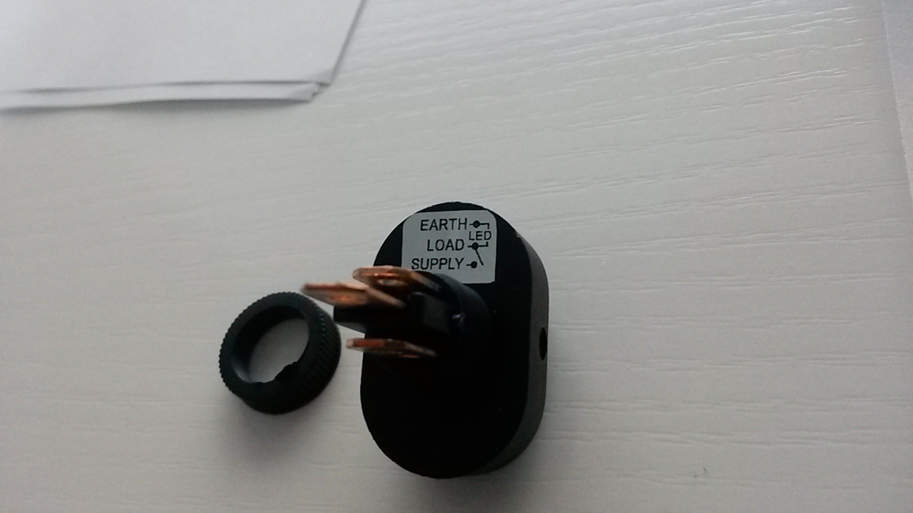
hello i bought this 12v switch http://www.banggood.com/12V-30A-LED-Light-Car-Boat-Auto-Rocker-SPST-Toggle-Switch-12mm-p-956774.html


i connected this in this way and the led is ON, and the bottom barrel is WITH current. so basically the switch is at ON STATE. and no cable heats up.
Gz7K15g.jpg


t


hen i connect in this way, it should be OFF state. led is off, and bottom barrel is WITHOUT current. but unfortunately something heats up the cables... BOTH cables. why?
if led is nopowered,,, what current is passing throught the switch?
vSN4ui7.jpg


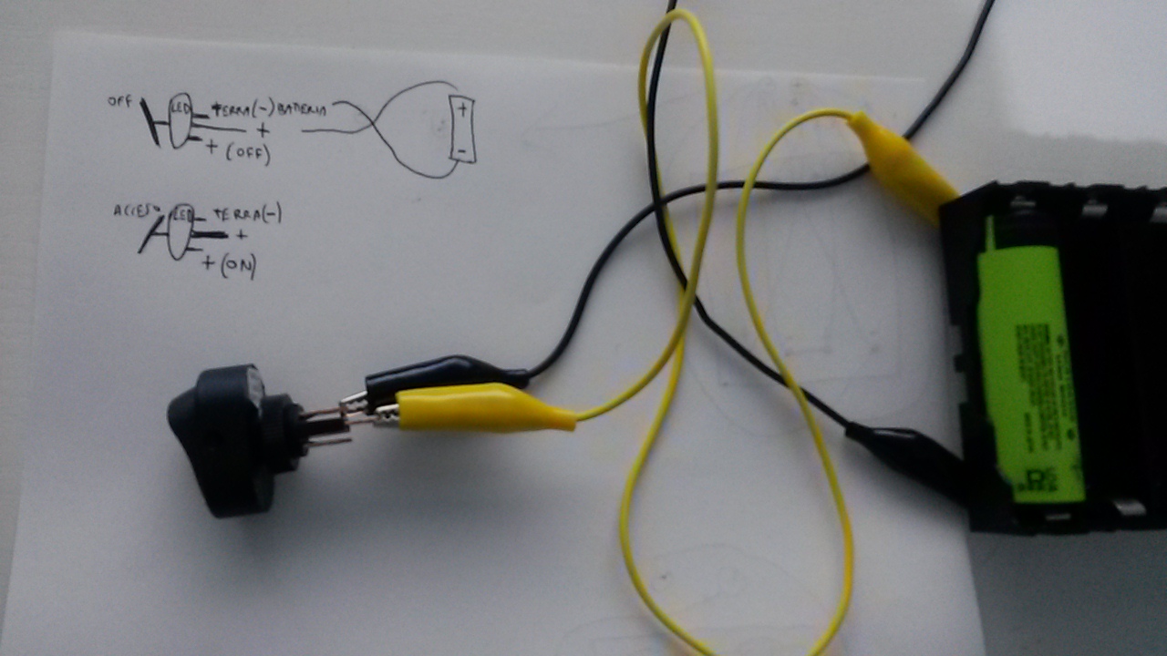
this is the precise scheme of the labeled switch. maybe i am doing some error?
a4g72dO.jpg


i don't understand if this switch is SUPPOSED .... that when OFF > led is ON or............when OFF> led is OFF .


please someone explain me. because i tryed another kind of connection with + pole of battery in bottom barrel, and - battery pole in higher barrel. THIS WORKS OK(in the central barrel current do pass when led is OFF....) but in this way the led is ALWAYS ON WHEN IN OFF STATE. it could be supposed to be used in a "car".... but i need to use with a battery so i can't always power that led.... would drain all battery in weeks.......
 
Last edited:

Keisari

Newly Enlightened
Joined
Feb 12, 2015
Messages
32
It's not obvious what you are trying to accomplish, as only a part of your circuit is shown.

However, with that switch type, you should have 3 wires connected, unless you are omitting the signal lamp. 2 connectors are meant to switch your load, i.e. they are the actual switch. The third one is to operate the signal light. Depending on switch type and your circuit, this can be wired to only come on when the switch is on or always on. Typically the former is desired, but the latter is sometimes handy for ergonomics reasons. For example in automotive applications where it is not easy to locate a switch without directly looking at it when it's dark.

What you have done here does not make any sense, to put in bluntly. If you are only using 2 wires to the switch, you should connect them into "load" and "supply", where supply is your battery positive and load goes to your... well, load. The signal light is not used. If you want the signal light as well, the "earth" connection is to be connected to your battery negative.
 

nein166

Flashlight Enthusiast
Joined
Feb 16, 2006
Messages
1,575
Location
New York
Working off your last picture
SUPPLY = positive battery
EARTH = negative battery
LOAD = Light Positive (but not the switch light)
The battery gets connected to (bottom +) and (Top -)
What you want to turn ON is connected to (center+) and (Top -)

Since it is designed to work in a car the green LED might always stay on since a car has a Key to turn on all the Acc power it won't drain the battery when the key is out
So you would need to put a second switch along positive battery wire to kill your battery pack power
 
Last edited:

Keisari

Newly Enlightened
Joined
Feb 12, 2015
Messages
32
Since it is designed to work in a car the green LED might always stay on since a car has a Key to turn on all the Acc power it won't drain the battery when the key is out
That's possible but unlikely and would mean that the sticker in the last picture is incorrect.

If the switch is like it should be based on that picture and it is wired the way you (or I) described, the signal light will illuminate when the switch is closed(i.e. ON) ja remain dark when the switch is open(i.e. OFF).

It is also possible to have the signal lamp on all the time. This would be accomplished by flipping the "supply" and "load".
 

Keisari

Newly Enlightened
Joined
Feb 12, 2015
Messages
32
After reading through the original post again, I sort of feel stupid, as my previous replies have not been at all directly useful. :eek:

I know understand the switch is actually acting erratically. Have you thought about the possibility of the sticker(and, because of that, the switch itself) being upside down? This would explain the situation where your signal light is off and there is a high current heating up the alligator wires(your battery being in a short circuit situation, really). I don't know why the light would remain on in the other switch position in that case, but maybe the internal connection is different from what is shown.

Sorry for double posting, it appears I'm unable to edit my previous reply.
 

nein166

Flashlight Enthusiast
Joined
Feb 16, 2006
Messages
1,575
Location
New York
... possibility of the sticker(and, because of that, the switch itself) being upside down?

We definately don't know enough about the switch but I was baffled by the wires heating up, Keisari I think you have figured out the explanation with the sticker being on backwards causing a short circuit, sharp thinking
 

PMM

Newly Enlightened
Joined
Feb 17, 2009
Messages
31
not sure what is happening in the switch but correct wiring would be power and earth to the outer tabs and the device to be powered gets the middle lead.

so battery to the outer and e.g. a motor connected to middle and earth when switch clicked led should be on and motor spinning.

if the label was reversed your would be seeing no led as you have no earth supply to the led.

question I cannot answer is why when the switch is on you get a short in would have thought the led would have blown.
 
Last edited:

more_vampires

Flashlight Enthusiast
Joined
Nov 20, 2014
Messages
3,475
Confusing thread is confusing.

The wires are getting hot? That's a short. Hooking the battery + and - to LOAD and SUPPLY would short the battery when you turn the switch on. This configuration blows up big power supplies.

Circuit is incomplete. Load device would be placed in series with the battery pack. OP is running without a dummy test load.
http://en.wikipedia.org/wiki/Dummy_load

(That's not an insult, by the way. It's what the component is called.)

The way it's wired now, you are dead shorting the battery.

Oh wait... am I the confused one now? :(
 

Keisari

Newly Enlightened
Joined
Feb 12, 2015
Messages
32
Good to see it's not just me who is very confused.

One more thing I don't remember being mentioned yet is that in OP's test setup there is a situation that would never occur in typical practical applications. When the switch is OFF, there should be no voltage across the LED(i.e. between "earth" and "load"), because voltage is supposed to be connected to "supply" and not "load" post.

Therefore the switch could make contact between the EARTH and LOAD posts in OFF state even by design. I'm again contradicting myself, this time assuming the sticker is NOT reversed. :grin2:
 

PMM

Newly Enlightened
Joined
Feb 17, 2009
Messages
31
this is how the circuit should be working..

removed(pmm)

See Rule #3 Do not Hot Link images. Please host on an image site, Imageshack or similar and repost – Thanks Norm
 
Last edited:

realista

Enlightened
Joined
Aug 16, 2014
Messages
208
thank y very much to all members who helped me in this thread. thank you PMM wor the scheme!
however now i know the correct way to connect it.
Battery + goes to "Supply", battery – goes to "Earth" and "Load" is used for, well the load!. and the sticker is correctly positioned! and led turns on only when switch is ON.

problem solved!


a4g72dO.jpg
 

Latest posts

Top