
DIWdiver
Flashlight Enthusiast
Hi all,
A CPF member has asked for my help. He wants to build a simple fade-in circuit for a 24V LED string, using a '555 timer. In our communications, I came to think this is to provide a gradual ramp up in brightness when turned on. There was no requirement for gradual turn-off, so turn-off is sudden.
A 555 timer is great for providing PWM dimming, but there are a few issues:
1. I couldn't find a version that runs on 24V (max is 18V).
2. I couldn't find a published fade-in circuit.
3. We need to drive the LED at higher current and voltage than the 555 can handle by itself.
4. The basic 555 circuits aren't good at producing low duty cycles (DC) needed to substantially dim an LED.
Here's my answer, for all to see and comment on:
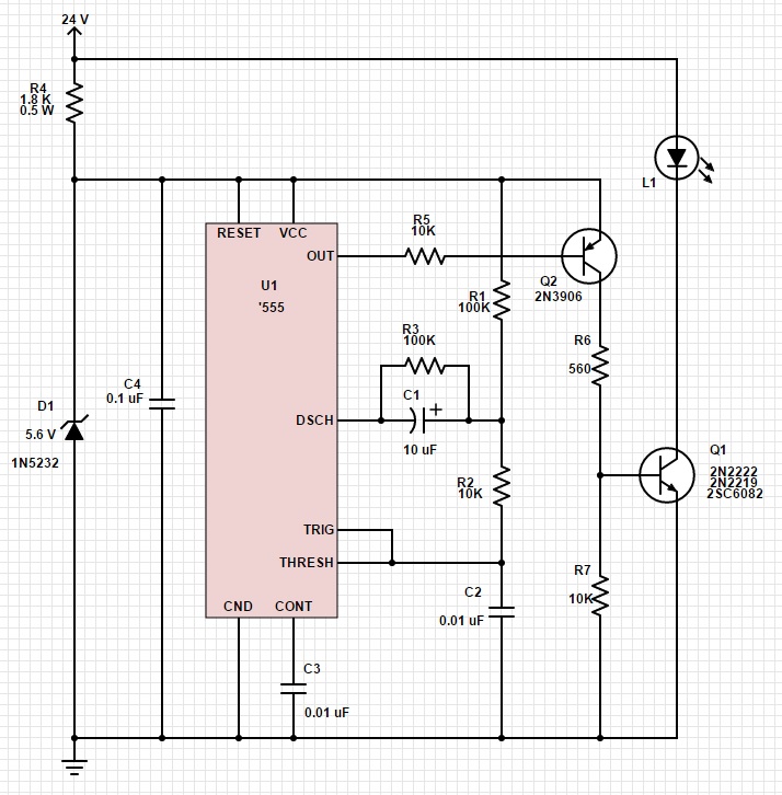
It's the standard astable timer (oscillator) circuit from the 555 datasheet, with some mods.
R4 and D1 provide a 5.6V supply to run the 555.
Q1 provides the higher voltage and current we need.
Q2 inverts the output, turning a high DC into a low DC (and vice versa).
The fade is provided by C1. When the circuit is first powered up, C1 is discharged, and looks like a short circuit. This makes the core circuit look like the standard high-DC astable, and because of Q2, this provides a low DC at the LEDs. With the values shown, the circuit powers up with a DC of about 9% on the LEDs.
Over time, C1 charges up and the DC starts to increase, eventually reaching 100%. A value of 10 uF gives about 1 second fade-in. The fade-in time is proportional to the value of C1, so adjust accordingly.
R3 is in the circuit to ensure that when the circuit is powered off, C1 fully discharges. It's probably not actually necessary, but I put it there to make sure there's a defined time that it will take to reset the fade-in. The value should be at least as high as R1 to prevent disturbing the circuit operation, but could be higher. When you turn the circuit off (by removing the 24V power), C1 will discharge rapidly at first and then more and more slowly according to the well-known RC decay curve. If you turn the power off and back on rapidly, the DC will come back near or perhaps even at 100%. The longer you leave it off, the lower the initial DC will be at turn-on. With the values given it takes about 10 seconds to fully reset.
Some notes on selecting parts:
The voltage of D1 is not critical, though I wouldn't suggest less than 5V, even if your '555 will operate at 2V. You could go as high as the '555 specs allow, which varies according to which variant you get. Make sure you check the data sheet for the exact part you get. The max supply voltage can be as little as 5.5V. The value of 5.6V was chosen as it supports nearly all variants. If you change the voltage, you should also change R4 and R6.
There are literally hundreds of different transistors that could be used for Q1. The three parts I suggested were chosen as follows:
The 2N2222 has been widely used for decades, and is still popular. In this circuit it can handle the 250 mA load that was originally requested (actually he said up to 6W at 24V, which gives 250 mA). Here it's good for up to 300 mA.
The 2N2219 is essentially identical, but if you get it in the original metal can package (which might be getting difficult) it has better heat handling ability, and could handle about 400 mA here.
The 2SC6082 is a bigger part and can handle up to 2A.
The circuit could easily be scaled to higher currents and voltages. Let me know if you want some suggestions.
The circuit was designed for a low-power variant of the '555, with a supply current less than 1 mA. Roughly half of the variants fit this requirements. Anything with TLC555 or 555C in the part number should be okay. The common LM555 and NE555 are NOT low power. To run a part with supply current up to 10 mA (this covers the large majority of variants), change R4 to 1K, 1W.
I hope this answers the original request, and maybe sparks something beyond that!
D
A CPF member has asked for my help. He wants to build a simple fade-in circuit for a 24V LED string, using a '555 timer. In our communications, I came to think this is to provide a gradual ramp up in brightness when turned on. There was no requirement for gradual turn-off, so turn-off is sudden.
A 555 timer is great for providing PWM dimming, but there are a few issues:
1. I couldn't find a version that runs on 24V (max is 18V).
2. I couldn't find a published fade-in circuit.
3. We need to drive the LED at higher current and voltage than the 555 can handle by itself.
4. The basic 555 circuits aren't good at producing low duty cycles (DC) needed to substantially dim an LED.
Here's my answer, for all to see and comment on:
It's the standard astable timer (oscillator) circuit from the 555 datasheet, with some mods.
R4 and D1 provide a 5.6V supply to run the 555.
Q1 provides the higher voltage and current we need.
Q2 inverts the output, turning a high DC into a low DC (and vice versa).
The fade is provided by C1. When the circuit is first powered up, C1 is discharged, and looks like a short circuit. This makes the core circuit look like the standard high-DC astable, and because of Q2, this provides a low DC at the LEDs. With the values shown, the circuit powers up with a DC of about 9% on the LEDs.
Over time, C1 charges up and the DC starts to increase, eventually reaching 100%. A value of 10 uF gives about 1 second fade-in. The fade-in time is proportional to the value of C1, so adjust accordingly.
R3 is in the circuit to ensure that when the circuit is powered off, C1 fully discharges. It's probably not actually necessary, but I put it there to make sure there's a defined time that it will take to reset the fade-in. The value should be at least as high as R1 to prevent disturbing the circuit operation, but could be higher. When you turn the circuit off (by removing the 24V power), C1 will discharge rapidly at first and then more and more slowly according to the well-known RC decay curve. If you turn the power off and back on rapidly, the DC will come back near or perhaps even at 100%. The longer you leave it off, the lower the initial DC will be at turn-on. With the values given it takes about 10 seconds to fully reset.
Some notes on selecting parts:
The voltage of D1 is not critical, though I wouldn't suggest less than 5V, even if your '555 will operate at 2V. You could go as high as the '555 specs allow, which varies according to which variant you get. Make sure you check the data sheet for the exact part you get. The max supply voltage can be as little as 5.5V. The value of 5.6V was chosen as it supports nearly all variants. If you change the voltage, you should also change R4 and R6.
There are literally hundreds of different transistors that could be used for Q1. The three parts I suggested were chosen as follows:
The 2N2222 has been widely used for decades, and is still popular. In this circuit it can handle the 250 mA load that was originally requested (actually he said up to 6W at 24V, which gives 250 mA). Here it's good for up to 300 mA.
The 2N2219 is essentially identical, but if you get it in the original metal can package (which might be getting difficult) it has better heat handling ability, and could handle about 400 mA here.
The 2SC6082 is a bigger part and can handle up to 2A.
The circuit could easily be scaled to higher currents and voltages. Let me know if you want some suggestions.
The circuit was designed for a low-power variant of the '555, with a supply current less than 1 mA. Roughly half of the variants fit this requirements. Anything with TLC555 or 555C in the part number should be okay. The common LM555 and NE555 are NOT low power. To run a part with supply current up to 10 mA (this covers the large majority of variants), change R4 to 1K, 1W.
I hope this answers the original request, and maybe sparks something beyond that!
D
")