
Hi guys,
Thanks for your help on various aspects.
I'd like to tell a little about my build, struggles and choices, some of it might help you not to run into the same problems.
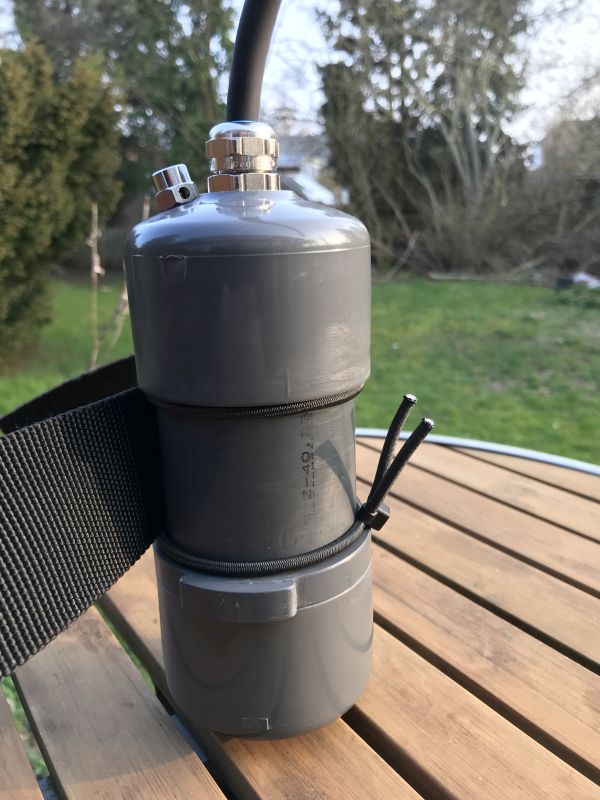
My goal was to build a canister for heating, based on available plumbing materials, as I have no access to a lathe.
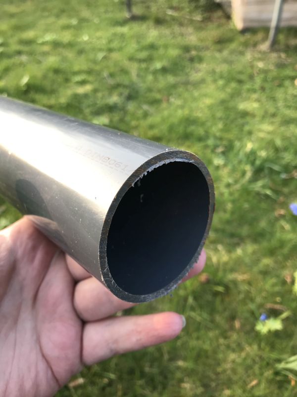
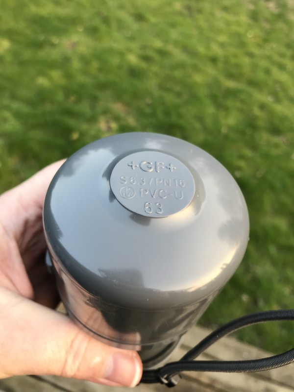
The choice fell on 63mm GF industrial PVC 10bar pipe.
As I have no lathe, it's hard to make a location for an o-ring. So I accepted to glue it together and charge it through the e/o cable.
To me it seems like the O-ring where you open for every dive is the vulnerable spots in camera housings and lamps. So I'd prefer not to have to open the water tight barrier every time.
On the other hand, you miss the possibility to look inside, to notice if something odd is going on.
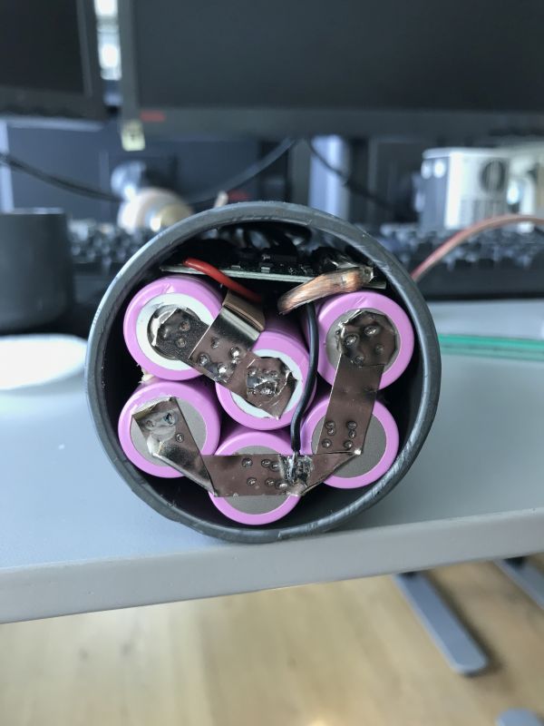
It can hold 7 18650 cells in one "layer" or you could call it a flower, a ring of 6 cells with one in the middle.
Unfortunately minimum buy is 5m, so I have some for new experiments...
Selected Samsung 3400/3500mAH cells.
Going for a Santi-compatible heat vest, requiring "12V", which is 3 cells or nominal 10.8V. And 3 hours of use (two dives and surface interval) with 40-50W of power consumption prescribes 4 parallel cells.
This can be done in the selected tube with two "layers" of cells with 6 in each.
Next step was to point weld the batteries.
We have some serious lab powersupplies for automotive eqpt. at work, 15V 100A, so I thought that could do it - optionally two in parallel. It just heated the strips - no welding.
So I had to make a welder:
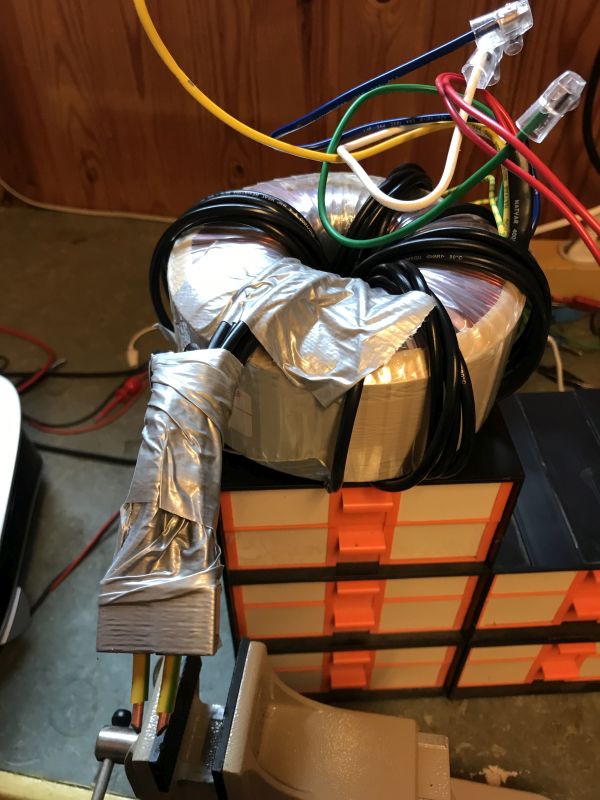
I had this 500VA ring core trafo at home from an AMP building project nearly 30 years ago. On a ring core, you can simply add a new secondary winding by winding through the hole, you don't need to remove the old secondary to get space for it - just don't connect the old secondary windings.
It makes 0.5V/turn, I saw some other projects doing 1.5-3V, 2V measured during welding at a professional unit, so I went for 2.5V. 5 parallel wires of 4 square mm, 20square mm Cu in total.
Primary goes through a spring loaded lighting switch (those for kip relay lighting systems), used as a foot switch. A very short bump on the foot switch is enough:
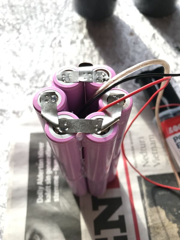
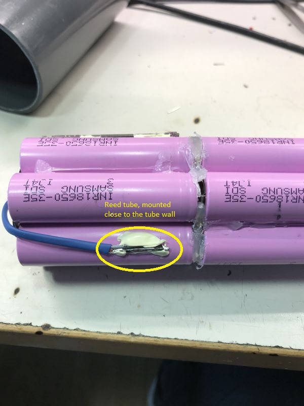
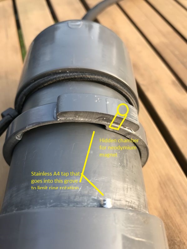
Now, as I found a nice protection board on ebay that would fit in the middle, and as the only place in these pipe end cups to place a gland or a piezo switch is in the middle, I went for the 6 cells in a ring setup - this should later prove to be a bad decision..
OK, next step is the gland. Wanted something with a long thread to be able to put a counter nut on the inside. And capable of handling Thor 9.6mm e/o cable
https://www.deepstop.de/en/light-accessories/945-eo-cords.html
Couldn't find Agro from reasonable sources. One of the few I could find was this:
https://se.lappgroup.com/fileadmin/documents/technische_doku/datenblaetter/skintop/DB53112005EN.pdf
After I bought them, I found that they seal using plastic against a brass cone, and I simply don't trust it.
I then heard that "blueglobe" glands have a good reputation among rebreather divers. So I bought some of those:
https://www.ibs-gruppe.de/shop/kabelverschraubungen/blueglobe/776/bg-816ms
They seem to work.
I grinded the typing away, drilled in the middle, and made a M16x1.5 thread. Got a nice 7-8mm deep thread there.
Now in to the electronics.
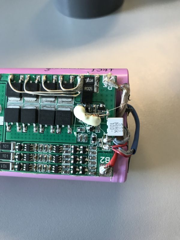
I bought these protection and balance boards:
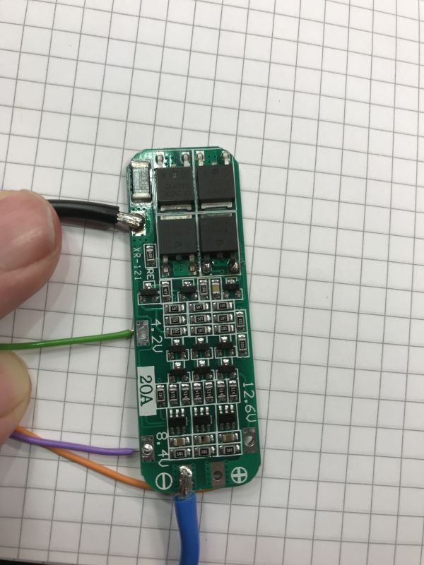
I got a bit suspicious when I saw that the power MOSFETs had the same name, but clearly were from different factories.
Currently it's hard to get MOSFETs due to allocations, and I've seen fake MOSFETs at work - re-branded, much weaker MOSFETs.
So I wanted to test functionality and power dissipation.
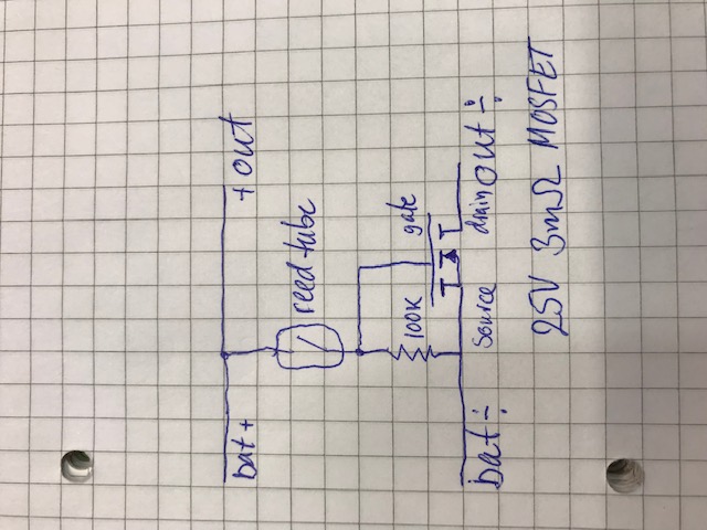
I didn't find any balancing current. So I made a schematic of the device, and realized that there is no balancing circuit on the PCB, even though the seller claims it.
Arrgh..
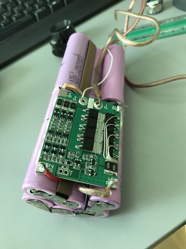
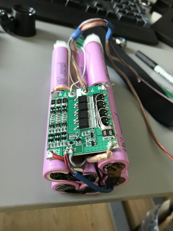
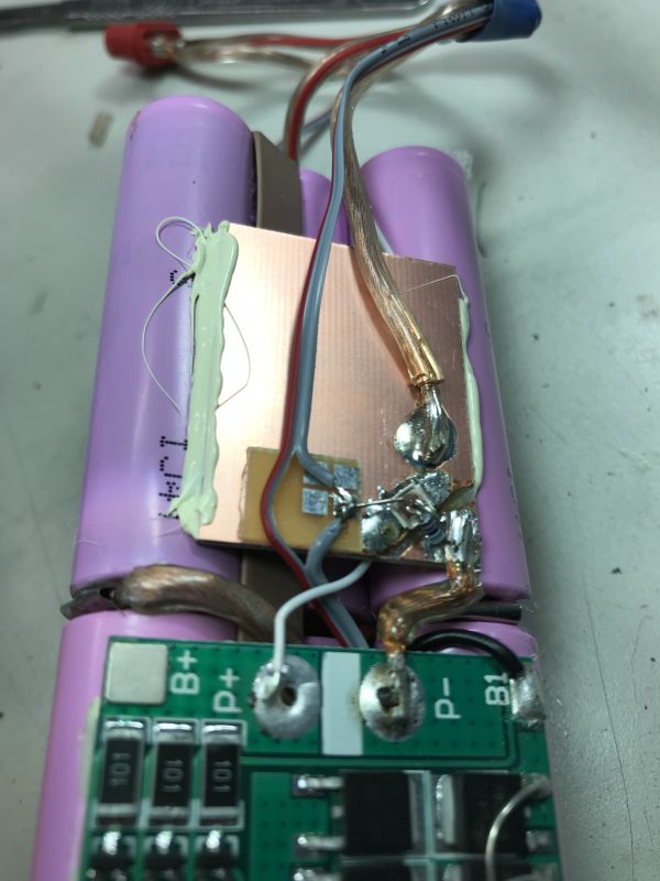
I had a very big 3S protection/balancing board in the drawer.
to use it, I had to re-arrange my 6 cells, and also cut some of the board away, and replace some power tracks with wires...
Continued in the next post
Thanks for your help on various aspects.
I'd like to tell a little about my build, struggles and choices, some of it might help you not to run into the same problems.
My goal was to build a canister for heating, based on available plumbing materials, as I have no access to a lathe.
The choice fell on 63mm GF industrial PVC 10bar pipe.
As I have no lathe, it's hard to make a location for an o-ring. So I accepted to glue it together and charge it through the e/o cable.
To me it seems like the O-ring where you open for every dive is the vulnerable spots in camera housings and lamps. So I'd prefer not to have to open the water tight barrier every time.
On the other hand, you miss the possibility to look inside, to notice if something odd is going on.
It can hold 7 18650 cells in one "layer" or you could call it a flower, a ring of 6 cells with one in the middle.
Unfortunately minimum buy is 5m, so I have some for new experiments...
Selected Samsung 3400/3500mAH cells.
Going for a Santi-compatible heat vest, requiring "12V", which is 3 cells or nominal 10.8V. And 3 hours of use (two dives and surface interval) with 40-50W of power consumption prescribes 4 parallel cells.
This can be done in the selected tube with two "layers" of cells with 6 in each.
Next step was to point weld the batteries.
We have some serious lab powersupplies for automotive eqpt. at work, 15V 100A, so I thought that could do it - optionally two in parallel. It just heated the strips - no welding.
So I had to make a welder:
I had this 500VA ring core trafo at home from an AMP building project nearly 30 years ago. On a ring core, you can simply add a new secondary winding by winding through the hole, you don't need to remove the old secondary to get space for it - just don't connect the old secondary windings.
It makes 0.5V/turn, I saw some other projects doing 1.5-3V, 2V measured during welding at a professional unit, so I went for 2.5V. 5 parallel wires of 4 square mm, 20square mm Cu in total.
Primary goes through a spring loaded lighting switch (those for kip relay lighting systems), used as a foot switch. A very short bump on the foot switch is enough:
Now, as I found a nice protection board on ebay that would fit in the middle, and as the only place in these pipe end cups to place a gland or a piezo switch is in the middle, I went for the 6 cells in a ring setup - this should later prove to be a bad decision..
OK, next step is the gland. Wanted something with a long thread to be able to put a counter nut on the inside. And capable of handling Thor 9.6mm e/o cable
https://www.deepstop.de/en/light-accessories/945-eo-cords.html
Couldn't find Agro from reasonable sources. One of the few I could find was this:
https://se.lappgroup.com/fileadmin/documents/technische_doku/datenblaetter/skintop/DB53112005EN.pdf
After I bought them, I found that they seal using plastic against a brass cone, and I simply don't trust it.
I then heard that "blueglobe" glands have a good reputation among rebreather divers. So I bought some of those:
https://www.ibs-gruppe.de/shop/kabelverschraubungen/blueglobe/776/bg-816ms
They seem to work.
I grinded the typing away, drilled in the middle, and made a M16x1.5 thread. Got a nice 7-8mm deep thread there.
Now in to the electronics.
I bought these protection and balance boards:
I got a bit suspicious when I saw that the power MOSFETs had the same name, but clearly were from different factories.
Currently it's hard to get MOSFETs due to allocations, and I've seen fake MOSFETs at work - re-branded, much weaker MOSFETs.
So I wanted to test functionality and power dissipation.
I didn't find any balancing current. So I made a schematic of the device, and realized that there is no balancing circuit on the PCB, even though the seller claims it.
Arrgh..
I had a very big 3S protection/balancing board in the drawer.
to use it, I had to re-arrange my 6 cells, and also cut some of the board away, and replace some power tracks with wires...
Continued in the next post
Last edited:
")
