Constant Current vs Constant Voltage LED Modules

SignQuest

Newly Enlightened
Joined
Apr 22, 2021
Messages
6
Hi everyone,

I'm trying to get a better understanding when it comes to Constant Current versus Constant Voltage LED Modules or systems, and when you are driving them using a typical Constant Voltage LED Driver to power them.

I tried to do some reading online and all I could find on the topic was related to CC & CV Power Supplies.

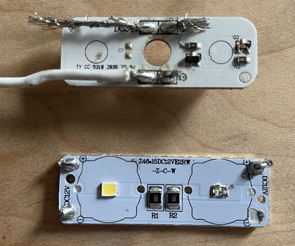
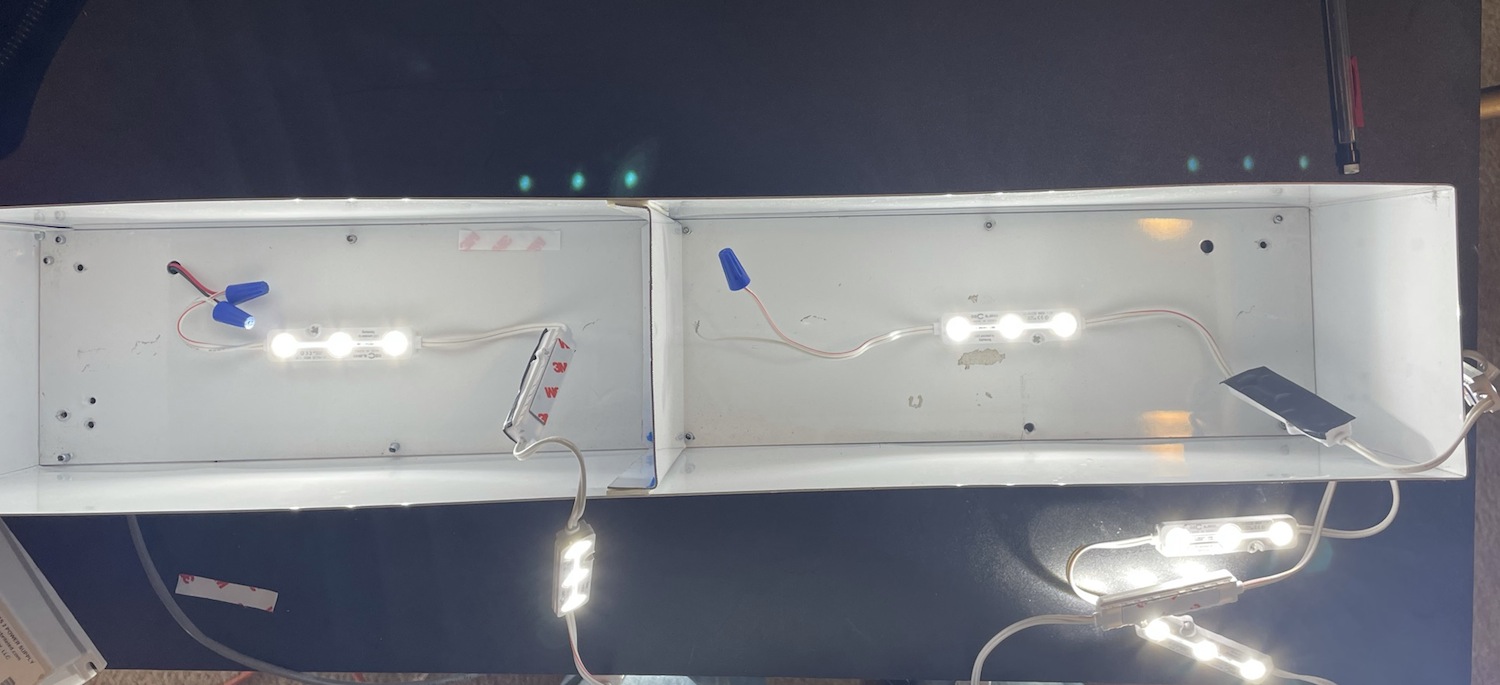
From my understanding CC LEDs have a onboard current regulator chip, as well as resistors that are for voltage? The current is what makes the LED bright. On a CC String of say 20 individual modules the first LED on that string will be just as bright as the last LED on that string creating consistent lighting?

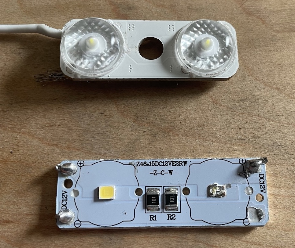
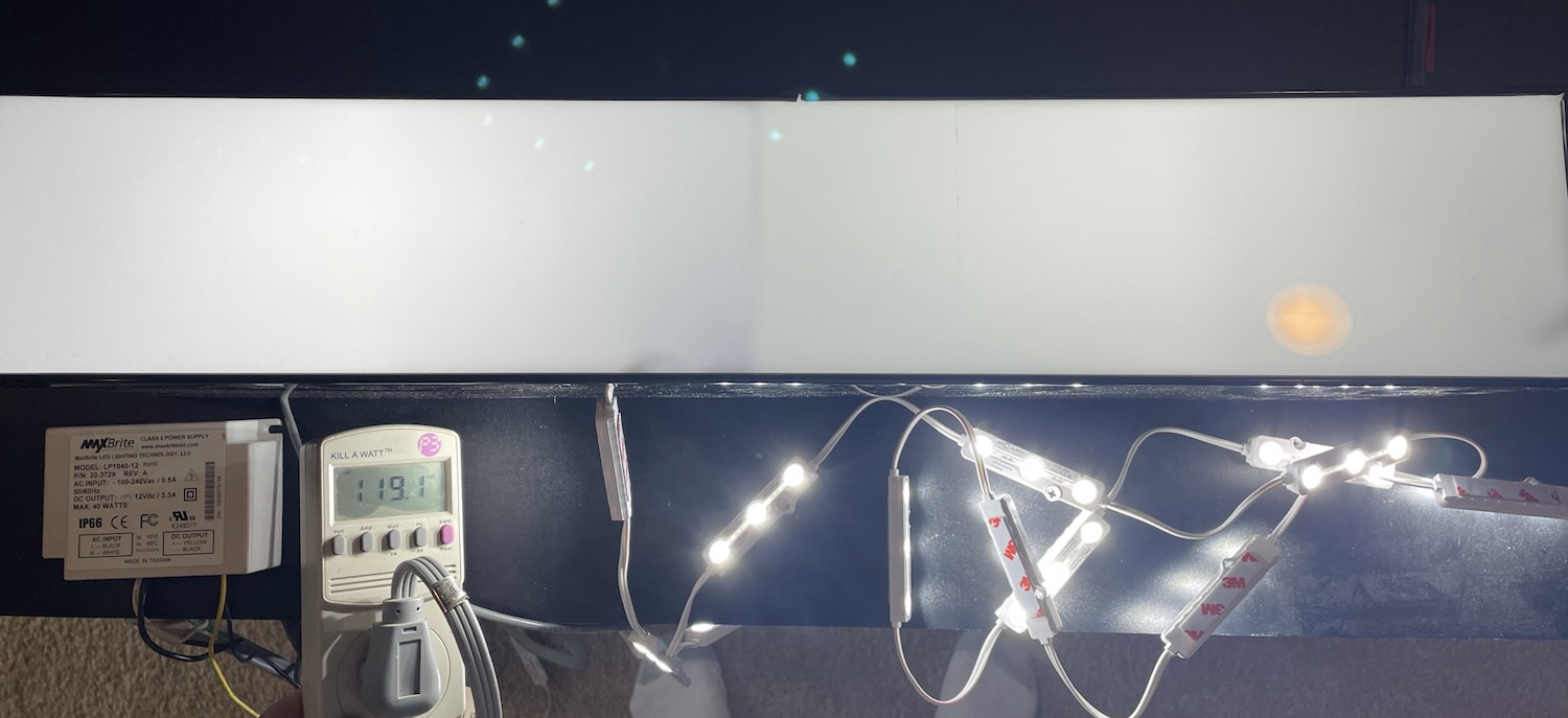
CV LEDs only have resistors which regulate only the voltage? and for anything over 12v brought (fraction of a volt) to the LED just makes the LED module hotter? With no current regulator these modules seem to have a short life than CC LED Modules, and lumen maintenance takes it's toll faster. On a string of 20 LED modules the first module will be brighter than the last, correct? Is the first module taking a bigger hit than the last?

To get a better understanding of these two products can someone explain to me, or possibly fill in gaps what is going across the PCB boards (Current/voltage) on say two strings of 12v LED (1.2 watt 3 diode modules) are hooked up to a 12V 60w LED power each. One CC string to a power supply, and a CV String on the other supply.


I'm no engineer or major in electronics, but just trying to get a better understanding of them as they relate to my trade


Thank you in advance
 

Dave_H

Flashlight Enthusiast
Joined
Nov 3, 2009
Messages
1,371
Location
Ottawa Ont. Canada
LEDs are current-driven devices so trying directly to regulate voltage directly across them is not a practical way to control current/brightness.

Module designed to run from CV supply must have internal current limiting such as resistors, or linear or switching-type (for high efficiency) constant-current circuit.

Module designed for CC supply most likely does not have internal current limiting and should not be connected directly to a CV supply.

As far a brightness varying along a "string" of LED modules, with proper design this should not happen. If it is CV supply and voltage drops due to the wiring, modules further out see lower voltage and may be less bright, say in the case of resistor current control.

Taking your example of 12v supply and three LEDs (in series), the LEDs will drop about 9v or so and series resistors take up the difference, following Ohm's law, and dissipating power. Efficiency of this arrangement is not all that bad (about 75% or so) unless you raise the supply from 12v to say 14v (down to about 65%).

A module using linear constant-current regulator will also take up the voltage difference in the regulator but would provide better current control if the supply varies, down to some point where the regulator can't regulate and brightness decreases.

Module with switching regulator could provide a wide input voltage range and high efficiency with constant brightness, within certain bounds. It could be step-up or step-down depending on input voltage (range) and the number of LEDs and how connected (series, parallel, or series/parallel).

Dave
 

SignQuest

Newly Enlightened
Joined
Apr 22, 2021
Messages
6
I've heard something in the past and thought I would ask here.

In cases where users use long strings similar to the scenario I was asking about, 1 CV & 1 CC String but say a linear module length of 25 modules (3 diode modules) each using 18AWG Wire and 15' long.

Does the first module on that CV string take a bigger "hit" so to speak over the latter modules, where it can mean lesser life?


I'm really trying to find the pro's and con's of both LED modules.

Thank you
 

Dave_H

Flashlight Enthusiast
Joined
Nov 3, 2009
Messages
1,371
Location
Ottawa Ont. Canada
Still not too clear on the LED modules; are they designed for 12v constant-voltage? What do the specs say; is 1.2W for the module, or each LED? If you have the modules, what is marked on them?

Also not too sure what "taking a bigger hit" refers to. If you're running a string of CV LED modules from a 12v CV supply, the first LED will see 12v and others further down the line see lower voltage due to drop in the wiring, depending on its resistance and the current being drawn. The first module should not have shorter life if things are set up correctly. The one at the far end will take the biggest "hit" for reduced voltage, and possibly lower brightness.

A 12v 60W supply if regulated can supply anything up to 5A to the LEDs, whatever they draw. If the supply is not well regulated, yes the voltage could rise under light load and put more stress on the modules, making them run hotter (and possibly brighter, depending on how they are current-limited).


Dave
 

SignQuest

Newly Enlightened
Joined
Apr 22, 2021
Messages
6
Thanks for all info Dave,

Attaching a fe pics of typical LED modules, Top is the Constant Current (Fiberglass PCB), lower CV, second pic is the back of the CC Module (Aluminum PCB). I scrapped the diode getting the cast molding off

CC%20and%20CV%20Auto.JPEG


CC%20Back%20and%20CV%20Auto.JPEG


So, I took an old 40watt 12v PSU and hooked it up to two (24 count each or 28.8watts of LED Modules) LED strings, same mfg, one CC and one CV (12' - 9" length). They are 1.2watt modules.

I used a channel 24" x 4" x 5" Depth split the compartment evenly and used a acrylic face #7328 (typical sign grade surface). My wife happened to take off with my truck which had my meter in it. I took the first LED in each string and put it in one side of the compartment, and the last on the other side of the compartment.

Channel%20Overview.JPEG


Channel%20Open.JPEG


I used a ExTech Meter that I have and took a reading off the face (Luminance), instead of averaging the highs and lows I just went for the High's.


First was the CV version of the LED modules


First Module from the string

CV%20First.JPEG


Last Module of the CV String

CV%20Last%20.JPEG


First Module of the CC String

CC%20First.JPEG


Last Module of the CC String

CC%20Last.JPEG


Kill-A-Watt Meter stuff

34 Watts

KillaWatt%20Watt.JPEG


Volts
KillaWatt%20Volt.JPEG


Power Factor

KillaWatt%20PF.JPEG


So it looks like the variance is greater on the CV String from brightness first to last and it runs hotter? Wish I had my meter to see what voltage was was on the PSU, (I'll post later). The CC string seems to be more consistent with only a few Foot Candle difference.

The PCB on these particular modules are both fiberglass. I've run both in a similar compartment for 20 hours a day for somewhere around 22,000 hours of operation cycled twice a day. The CV LEDs (Four - 3 diode .72w LED Modules) degraded 17% from the original output at 17,480 hours, and the CC was almost 6% in 22,000 Hours (Six - 2 Diode .5w LED Modules)


A lot of times individuals in my trade are hooking up multiple strings of 25, 30 to 40+ modules all on one string and running them across sign cabinets and sign structures. I've always been int he belief to hook up no more than 20, maybe 25 is pushing it. I've always used CC rather than CV modules for anything unless I had a project that required a gradual dimming control and only CV Modules can provide that
 
Last edited:

idleprocess

Flashaholic
Joined
Feb 29, 2004
Messages
7,197
Location
decamped
Glancing at the boards, it appears that the difference between "CV" and "CC" in your case is that CV modules use resistors (and will be sensitive to input voltage) while CC modules have a basic active driver onboard and should provide constant current to the LEDs across a wide voltage range. So long as the voltage drop across long strings stays within spec, CC modules should provide consistent output throughout the chain.
 

Dave_H

Flashlight Enthusiast
Joined
Nov 3, 2009
Messages
1,371
Location
Ottawa Ont. Canada
Very interesting set of pictures SQ, and good testing, helps answer some questions.

The last CC LED module on a string should draw the same current as the first, so assuming the wiring drop is not too high, all modules should be the same brightness. The ones at the start may need to drop higher voltage internally so could run a bit hotter. I understand your question better now.

CV (resistor limited) modules at far end will see lower voltage and lower brightness, how much lower depends on module design and amount of wiring drop. Taking 25 1.2W (100mA) 3-LED modules over 15 feet of #18 wire (0.0065 ohms per foot, essentially lamp cord), estimated drop is about 0.3v. The last 12v module will see 11.7v. I further estimated end LED current would be about 10% less, may hardly notice.

Both CC and CV PCBs in the images have two LEDs. Are these lower i.e. approx. 0.5W power?

I notice the CC module uses classic 2-transistor current regulator. Current will vary with temperature, roughly 20% over 50C range (e.g. 0C to +50C). Resistor-limited circuit should vary much less, but is sensitive to voltage changes. Also, the CC transistor Q2 will be taking most of the heat, instead of a resistor, in some designs might impact lifetime if it gets too hot e.g. running higher than 12v, not likely in this case.

CV module appears to have two LEDs in parallel across 12v, each with 100 ohm series resistor. Each LED package must contain two or three series LEDs, single LEDs would be very inefficient and numbers wouldn't add up.

Dave
 

Dave_H

Flashlight Enthusiast
Joined
Nov 3, 2009
Messages
1,371
Location
Ottawa Ont. Canada
Calculation of wiring drop looks simple but a bit more complex than first thought. A number of variables affect accuracy, some not easy to determine. But assuming 1.2W CC modules draw around 100mA each, total drop should be about 0.25v to 0.3v, should have minor effect on CV module brightness, and no effect on CC module, as OP has found.

Calculation shows about half the total drop occurs in the first 30% of the chain, logical when you think about it as the upstream wires carry more of the total current, than towards the end. So using thicker wiring near the start could help, where drop is a concern.

I use a free circuit simulator from Texas Instruments (TI-TINA) which is good for things like this. Model was somewhat simplified. Accuracy depends on circuits used for LED modules. CC modules would be impacted mainly by temperature variation and component tolerance; for CV, LED characteristics would have greatest effect on current.

The 2-transistor CC circuit should regulate down to about 1v above the total LED voltage, down to 10-10.5v assuming 3 white LEDs in series. Not sure but for 2-LED PCB shown, I suspect each LED has three series chips, and two devices are driven in parallel. That could be confirmed by measuring. Two series LEDs would work in this circuit but not very efficiently; about half the power burned up in resistors or regulator. I have seen a design like this, hopefully these modules are better.

Perhaps the lighting industry has some simple calculator tools for wiring losses?


Dave
 
Last edited:

SignQuest

Newly Enlightened
Joined
Apr 22, 2021
Messages
6
Interesting program.

These 3 diode modules I think are using 3.5v chips in series for the 12v? They are also Samsung chips

Over the years I've tested various mfg LED modules and one thing that seemed to be a common point was the CV Modules were real sensitive when it came to ambient temperatures more so than the CC. Both would drop in light output during summer months, and rise in winter, but the CV modules seem to take more drastic changes than their counterpart.


This is probably a stupid question, but while I'm at it...

Sticking with this same lighting scenario I did above. When it comes to the CV Modules. If I only had 4 modules on a string (4.8w load) on a 60w CV PSU, would the current be higher in those 4 modules (making them brighter) than if I had 7 branches of 6 modules per string (42 modules 50.4 w load) pushing about 85% of the PSU?
 

Dave_H

Flashlight Enthusiast
Joined
Nov 3, 2009
Messages
1,371
Location
Ottawa Ont. Canada
Sticking with this same lighting scenario I did above. When it comes to the CV Modules. If I only had 4 modules on a string (4.8w load) on a 60w CV PSU, would the current be higher in those 4 modules (making them brighter) than if I had 7 branches of 6 modules per string (42 modules 50.4 w load) pushing about 85% of the PSU?

Using fixed supply with short 4-6- module strings, variation in current should be small. Relative brightness variation
down each strip and between strips should be small, maybe not noticable.

However depending on how well the dc supply is regulated, you might see some absolute brightness drop with
heavy load, across all modules/strips. A lot of supplies don't specify regulation. Doing some measurements could
help.

A "good" 12v supply should drop 0.5v or less at full load, or any substantial load you put on it, and supply should
be derated anyway. Typical supply is usually set a bit high (12.3v-12.4v) to partly compensate for wiring drop at
higher currents.

Dave
 

Dave_H

Flashlight Enthusiast
Joined
Nov 3, 2009
Messages
1,371
Location
Ottawa Ont. Canada
I opened a 5.5W (40W eq.) ac LED bulb from the "dollar store" which has plastic bulb easily cut off with a fine hacksaw. Inside are eight SMT LEDS (apparently) which on close inspection appeared to be duals, but voltage across each is 8.7v indicating they are actually triples (2.9v per die).

Bulb is non-dimmable and I don't have welder's goggles and even through 3 sets of sunglasses it was difficult to see individual die; but voltage gives it away.

For 12vdc these are convenient, probably used in some of these CC and CV modules. The 2-LED 0.7W CV modules in OP's images likely use something like this. Arbitrary number can be used as they are connected in parallel. With 100 ohm series resistors, each LED current would be around 30mA, which all adds up (12v x 0.03A x 2 = 0.72W).

Dave
 
Top