You are using an out of date browser. It may not display this or other websites correctly.
You should upgrade or use an alternative browser.
You should upgrade or use an alternative browser.
Which 1W LED has the highest LUMEN/Watt
- Thread starter mobile1
- Start date

I was reading the Cree documentation for their 1W parts, and it appears that the best binned 1W parts are suppose in the range of 67-73 lumens @ 350 ma or so. Does anyone know when Cree is scheduled to actually ship these parts en mass? I wouldn't mind picking up such a part..
I couldn't really find any Vf information in the Cree liturature. I didn't comb through it though, just a brief look over...
Edit: documentation is located here http://www.etgtech.com/pdf/Xlamp/XLamp7090_B&L.pdf
I couldn't really find any Vf information in the Cree liturature. I didn't comb through it though, just a brief look over...
Edit: documentation is located here http://www.etgtech.com/pdf/Xlamp/XLamp7090_B&L.pdf
Last edited:
idleprocess
Flashaholic
My understanding from NewBie is that the vast majority of 1W white Cree XLamp parts are ~3.4V @ 350mA. He's evaluated scads of them...
HarryN
Flashlight Enthusiast
The brightest 1 watt "LED" you can get is the one with the largest die area. For Lumileds, this is a Lux V, driven at 1 watt.
Lamina of course makes a "large area" package, which would be very efficient at 1 watt, at least I would guess it to be.
Lamina of course makes a "large area" package, which would be very efficient at 1 watt, at least I would guess it to be.
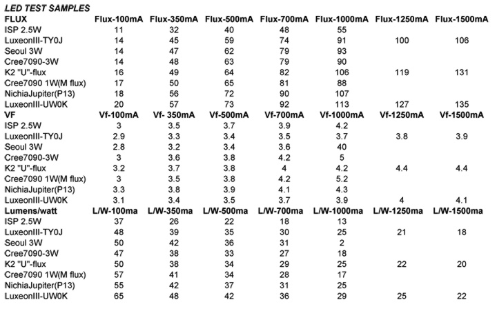
The highest efficacy is obtained in underdriving the LED's so I think I would agree that the 5W driven at 1W might well provide the most lumens. Although the table below is based on only one sample of each LED, I think there is some meat worth chewing on:
mobile1
Flashlight Enthusiast
Wow Don - thats an amazing list - I am blown away. Thanks a lot.:wave:
BackBlast said:I couldn't really find any Vf information in the Cree liturature. I didn't comb through it though, just a brief look over...
unfortunately it´s true...
Lumiled and cree led´s maybe have same typ. Vf at 350mA
but if you drive that led harder Vf varies a lot
https://www.candlepowerforums.com/threads/96091
That's a nice chart there. That's a really nice Luxeon III there, I didn't know you could get a U binned LIII. I appears that the XLamp M flux is within spec, perhaps the P flux would be too? Of course... availability might be similar to those U binned LIIIs.
It would be interesting to see a Luxeon V on that same chart.
It would be interesting to see a Luxeon V on that same chart.
Don,
YES! You confirmed my wierd measurements of 3 Cree XL3-7090s that I received. Their Vf at high current was unusually high. Newbie insisted that I was doing something wrong and/or there was something wrong with my measurement setup - but your Vf measurements of an XL3-7090 mirror mine - so it's not something here, it's actually the Crees themselves.
Great chart.
mobile1
Flashlight Enthusiast
Love all the knowledge in here.
What strikes me is how the real values differ to the advertised efficiencies. Shouldnt a couple of those be >50 L/w?
So which Cree should get the 70+L/W - is this the 7090-1W? Has anyone ever seen or got their hands on one of those?
What strikes me is how the real values differ to the advertised efficiencies. Shouldnt a couple of those be >50 L/w?
So which Cree should get the 70+L/W - is this the 7090-1W? Has anyone ever seen or got their hands on one of those?
Semiman,
I am using an Ocean Optics Spectrometer coupled with an Optronic 6" Integrating Sphere:
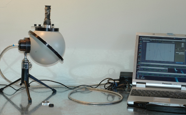
Now for calibration of the system, I used a calibrated incan source from OceanOptics and its accompaning "lamp file". The means of introducing this calibration lamp to the IS no doubt introduced error and some light loss. As a result, I am confident that my absolute measurements are off but by how much, I have no idea. The spectral response as well as relative comparisons however should be very close to reality.
In the case of the LED's measured above, they were all mounted on my "E-Screw" heat sinks and introduced to the IS with the same adapter (shown on the right in the pic below) :
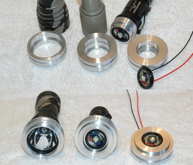
These heat sinks thread into the adapter and then the adapter drops down into the port on the IS. The IS is aluminium and the port is aluminium. I have not noticed any of the test pieces even getting really warm to the touch after some significant on time while mounted to the IS. Ambient temperature has been between 65 and 75 F for most of my testing and in the case above, it was probably in the high 60's for all tests.
That is a typo on the Seoul 2.5W LED. It should be 4.0 V
Now this test was interesting and I find it instructive to consider. However I want to point out that it is based on single samples of the various LED's and that variations in flux within a bin not to mention across the whole variation beyond specific bins significantly devalues these data points.
On an aside, this system was expensive to say the least and yet it would be considered by many to be a sensless toy and not worthy of use. These would be the folks that point out the shortcomings of $20,000 systems. I have found this humble system to be very instructive and the repeatability as well as predictible responses I have seen have supported my perception that I can glean valuable insight and information from its use. The integration sphere by its very nature allows for a much better and more comprehensive measure of light than say the meassures one gets from a lux meter. :shrug:
EDIT: I might as well throw in a table and graph I did on a UW0K sample which I find even more useful than the previous table.
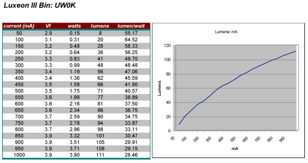
I need to point out that my digital bench supply is limited in resolution and control of current to 10's of miliamps and this is why the 50 mA measure is skewed. The actual current to the LED could have been as low as 46 mA or as high as 54 mA. I have another BK Precision bench supply that has resolution to three places but although advertised as 0 - 6 amps, the lowest I can set it is about 165 mA as I recall!  Man, I called them up and read them the riot act! How can you call it 0 to 6 amps when you can't get close to 0?!?! They should have rated it .200 to 6 amps!!
I am using an Ocean Optics Spectrometer coupled with an Optronic 6" Integrating Sphere:
Now for calibration of the system, I used a calibrated incan source from OceanOptics and its accompaning "lamp file". The means of introducing this calibration lamp to the IS no doubt introduced error and some light loss. As a result, I am confident that my absolute measurements are off but by how much, I have no idea. The spectral response as well as relative comparisons however should be very close to reality.
In the case of the LED's measured above, they were all mounted on my "E-Screw" heat sinks and introduced to the IS with the same adapter (shown on the right in the pic below) :
These heat sinks thread into the adapter and then the adapter drops down into the port on the IS. The IS is aluminium and the port is aluminium. I have not noticed any of the test pieces even getting really warm to the touch after some significant on time while mounted to the IS. Ambient temperature has been between 65 and 75 F for most of my testing and in the case above, it was probably in the high 60's for all tests.
That is a typo on the Seoul 2.5W LED. It should be 4.0 V
Now this test was interesting and I find it instructive to consider. However I want to point out that it is based on single samples of the various LED's and that variations in flux within a bin not to mention across the whole variation beyond specific bins significantly devalues these data points.
On an aside, this system was expensive to say the least and yet it would be considered by many to be a sensless toy and not worthy of use. These would be the folks that point out the shortcomings of $20,000 systems. I have found this humble system to be very instructive and the repeatability as well as predictible responses I have seen have supported my perception that I can glean valuable insight and information from its use. The integration sphere by its very nature allows for a much better and more comprehensive measure of light than say the meassures one gets from a lux meter. :shrug:
EDIT: I might as well throw in a table and graph I did on a UW0K sample which I find even more useful than the previous table.
I need to point out that my digital bench supply is limited in resolution and control of current to 10's of miliamps and this is why the 50 mA measure is skewed. The actual current to the LED could have been as low as 46 mA or as high as 54 mA.
I have another BK Precision bench supply that has resolution to three places but although advertised as 0 - 6 amps, the lowest I can set it is about 165 mA as I recall! Man, I called them up and read them the riot act! How can you call it 0 to 6 amps when you can't get close to 0?!?! They should have rated it .200 to 6 amps!!
Last edited:
mobile1 said:Love all the knowledge in here.
What strikes me is how the real values differ to the advertised efficiencies. Shouldnt a couple of those be >50 L/w?
So which Cree should get the 70+L/W - is this the 7090-1W? Has anyone ever seen or got their hands on one of those?
According to what I know, P flux 7090 (1W) is rated from 67-73 lumens. However, that's at 350 ma, and given the reported Vf of the Cree parts. You won't be seeing 70 lumens/watt out of them (really closer to 60-65). The actual efficacy of the part depends on the Vf required. What you are really buying is a 350 ma part, not a 1W part.
Now, I've never seen a P flux 7090. Nor have I seen a 65 L/W K2. Though I'd like to
idleprocess
Flashaholic
Cree XLamps are readily available whereas U-bin Luxeon IIIs are still a bit rarified and costly to obtain. Notice how the Cree parts closely match the easier-to-obtain TY0K emitter ... and still costs less.
Yeah, I know. The dreaded price/performance metric where many regulars here will pay anything for an unnoticable 10% more performance...
Yeah, I know. The dreaded price/performance metric where many regulars here will pay anything for an unnoticable 10% more performance...
idle ... yes, the mass-market argument won't work with us here
I am not a Lumileds fanboy, I am just wondering why all those great news about other manufacturers I am hearing for more than a year now don't transform into a widely available product that is actually clearly superior to the LuxIII ... including Vin, color tint, etc.
bernie
I am not a Lumileds fanboy, I am just wondering why all those great news about other manufacturers I am hearing for more than a year now don't transform into a widely available product that is actually clearly superior to the LuxIII ... including Vin, color tint, etc.
bernie
chimo
Flashlight Enthusiast
Don, thanks for sharing your testing results. These would have taken a good deal of time to run through - your effort is very much appreciated!
BTW, that Nichia Jupiter posted some impressive results.
Paul
BTW, that Nichia Jupiter posted some impressive results.
Paul
I believe the Luxeon U bin LuxIII claims the roost at present. However, if one were to buy a Luxeon light at target and a Nichia based light at target, it could well be that the Nichia would appear brighter to the customer than the Luxeon light. If the Luxeon were a S bin and the Nichia were a P12 for instance.
Although the numbers provide for obvious ranking, real world evaluation would not see the differences that the numbers imply; I think we all agree on this. To me, the one single advantage that still goes to Lumileds is that of tint consistancy throughout the beam. EOS is the deciding factor. However, I understand that the others are making headway in this regard and if one of the others can do something with magic sized nano crystals, all bets are off.
I suspect that a year from now, the elements and subject of this thread will seem like old history!! I know some CPFer's feel that nothing is really happening anymore and that we are just seeing repackaging and rehashing of the same stuff but at one level, a flashlight is still just a flashlight. On closer inspection though, the ride is no where near over and there are still some interesting curves ahead!
Similar threads
- Replies
- 7
- Views
- 1K