18650 battery configuration

Deeperdiverdude

Newly Enlightened
Joined
Oct 22, 2011
Messages
17
Hi All,

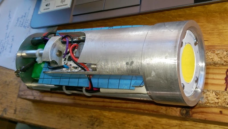
I am making a Mk 2 dive video light this time using the Bridgelux Vero array with a TaskLED driver and want to package as much battery life as I can into my cannister.

Physically there is enough room for 12 18650 cells but I could do with some advice as to the best way to configure them:

Either as option 1 - 4s/3p configuration and using a single battery protection module - will there be any issue with having three parallel cells in each branch?

Or option 2 - having three individual 4s/1p packs each with its own battery protection module and then collect all the outputs from the modules in parallel?

Thanks for any info or sugestions

Tony

PS - this is a video from inside the SS Thistlegorm with my Mk1 video light using 4x Cree xmls and TaskLED driver
 

DIWdiver

Flashlight Enthusiast
Joined
Jan 27, 2010
Messages
2,725
Location
Connecticut, USA
Wow! Awesome video and what a cool wreck.

Paralleling LiIon batteries is pretty safe, as long as they are at pretty much the same voltage when you connect them. It's the series connection that's problematic, and requires the balancing circuits.

So either of those configurations is fine. Three separate modules provides a little reliability advantage in that if a cell or protection circuit fails, it only takes out a third of your pack, and it's a bit easier to repair.
 

Deeperdiverdude

Newly Enlightened
Joined
Oct 22, 2011
Messages
17
Thanks for the replys, fyi this is my mk1 light. I
0yTCqsyhjbVD82JA859YGfaz_jKntRc30Ww6Y-uQt8BwIE8lFDPgOfQis-LzXmv3b_V3vwciUTc=w2560-h2560
learnt a lot from making it
edit

Tony
 
Last edited:

clawnfish

Newly Enlightened
Joined
Nov 28, 2014
Messages
18
Location
Europe
Hi Deeperdiverdude,

I'm planning on building ( or better say putting together ) a video light using the
Bridgelux Vero 100W ( or around ) COB. If you don't mind I have a few questions.

I need to provide the dimensions for the housing to a friend of mine and looking at the size of the COB and the actual LED module, it seems like I need to use a 80x10 or a 90x12 lense to be able to get the full 120 degrees beam of it. I reside in Europe and couldn't find 80x10 lens and if possible I don't want to increase the size of the light head by using the 90x12 lense. So, what size of lens will you use and do you know where I can find a 80x10 lense ?

The other question is in fact more related to this topic. I want to tell first that my knowledge on electronics is limited to W = I x V :) so I may be saying something completely silly below and also I assume you are using one of the 100W Veros.

You say you are planning to use 4S 18650 cells which adds up to 16Volts ( in fact as they drop quickly to 3.7 Volts , we can use 14.8 Volt ) if you are planning to use one of those around 100Watt COBs, the output V is around 42.5V @ the output current of 3A. So considering the efficiency ( 90% assumed) of the driver the input power will need to be :

42.5x3/0.9 = 142 Watt

So the input current using 4S 18650 will be :
142 / 14.8 = 9.6 A ( even more when they go down to 3 Volts or less )
As much as I know , none of the Taskled drivers can handle more than 7 A input current. After a lot of thinking I decided to use 5S2P but even that is not high enough input voltage for the above calculation ( 142/(3.7x5)= 7.7A and will increase until the end of the dive) . If you want to use HBFlex which allows maximum 24V input and George put in big bold letters not to use more than 5 Li-ion in series. So how are you planning to overcome this , assuming you also want to be able to get as much light as possible from the COB ?

Another thing I want to ask is about the final battery pack and the protection circuit wiring. As I mentioned above I am not familiar with electrics/eletronics. Is there a document out there that explains how one should wire this battery pack to the protections circuit ?

Thanks
 

DIWdiver

Flashlight Enthusiast
Joined
Jan 27, 2010
Messages
2,725
Location
Connecticut, USA
Did you do the calculation 42.5V x 3A = 127.5W? You said that's the only thing you know, and yet it looks like you plan to run a 100W array at 127.5W. Am I missing something? Are you planning to overdrive it that far?

Are you planning on a narrow beam video light? Most of the video light I've seen don't use lenses.
 

clawnfish

Newly Enlightened
Joined
Nov 28, 2014
Messages
18
Location
Europe
Did you do the calculation 42.5V x 3A = 127.5W? You said that's the only thing you know, and yet it looks like you plan to run a 100W array at 127.5W. Am I missing something? Are you planning to overdrive it that far?

Are you planning on a narrow beam video light? Most of the video light I've seen don't use lenses.

Hi DIWdiver.
I meant, around 100W. 42.5 Volts at 3A is an approximation I get from the actual datasheet of the COB LED module I am planning to use.
Look at page 12, in the graph, the MAX curve at 3A shows about 42.5 Volts and I used it to get the worst case scenario ( or the best case scenario if you will ) assuming HBFlex will be used which goes up to 3A output current:
http://www.bridgelux.com/wp-content/uploads/2013/10/DS33-Bridgelux-Vero-29-Datasheet.pdf

Please let me know if I am way off with my calculations.

About the "lens" I meant the front glass which will be a flat glass circle, so no "lenses" to focus the light. And the led module will be almost touching the front glass to get the widest possible beam.

Thanks
 

Deeperdiverdude

Newly Enlightened
Joined
Oct 22, 2011
Messages
17
Hi, sorry for late reply, although I will be using a 100w vero I doubt that I will be using its full capacity but it allows me flexibility. The beauty of the Taskled drivers is that you can choose from various current tables.
My lights dont use any lenses or columnators (sp?), as mentioned above video lights dont want any hot spots.
I would prefer to go 5s but that would make packaging inside my housing difficult.
 
Last edited:

clawnfish

Newly Enlightened
Joined
Nov 28, 2014
Messages
18
Location
Europe
Thanks Deeperdiverdude. Off topic but, I am trying to build more or less the same light as you are working on as I mentioned and I couldn't decide the design of the light head, where to put the magnetic switches, how thick should i have the part that will work as the heatsink for the LED and the driver circuit, etc. If that is not a problem, can you share a few photos of your light head ?
Re wiring of the PCM there is quite a lot of stuff on the web, this is typical
https://s.yimg.com/lo/api/res/1.2/_...uctimages/pcb/32105_wiring_diagram.JPG.cf.jpg
 
Last edited:

Latest posts

Top