
minisystem
Newly Enlightened
- Joined
- Jul 12, 2011
- Messages
- 96
After months of fiddling, I built a prototype of my flashing dynamo circuit on a PCB. Build photos:
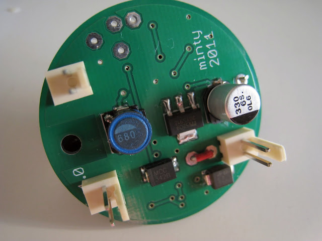
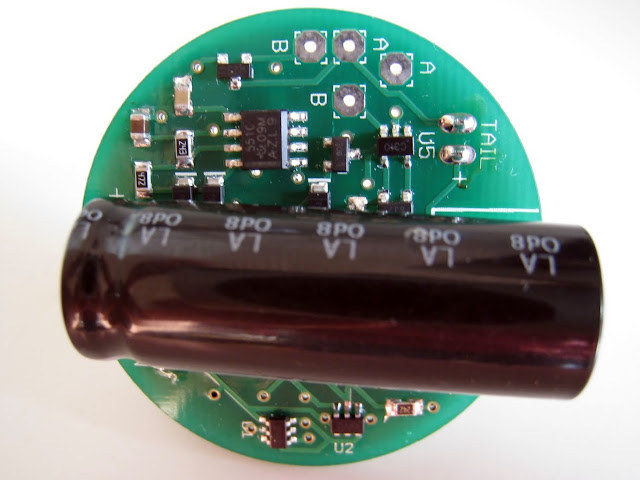
It works! The standlight is usefully bright for just over 2 minutes in solid mode and about 4+ minutes in flashing mode.
The only major issue I need to work through is with the 6.8V Zener diode that regulates the input voltage. With the LEDs connected, the dynamo voltage is Vf of the LEDs (around 5V), which is below the zener voltage, meaning the Zener isn't shunting any current. When in flashing mode, the dynamo voltage jumps during the off cycle (no load) and the Zener shunts all of the current. I'm using a 5W zener. If I understand correctly, the Zener's current will be the saturation current of the dynamo (0.5-0.6A) and the power will be that current multiplied by the zener voltage, so (6.8V x 0.6A =) 4.08W. Is that correct?
It's shunting this current a little less than half the time. Still, it gets too hot to touch. After several minutes it has yet to fail, but it makes me a little nervous. Not sure what to do with that dynamo output during the off cycle. A more elegant solution would be to capture it and pump it back into the LEDs in a burst, but I dont' know how to do that. If the zener does fail I'll have to find another way of dissipating or recycling the dynamo power during the off period of the flash. Any ideas?
Last edited: