Heat transfer in divelight head

DIWdiver

Flashlight Enthusiast
Joined
Jan 27, 2010
Messages
2,725
Location
Connecticut, USA
I used the Polymer Optics lenses in my light. I was very disappointed in the beam quality - lots of rays and other irregularities. They aren't too bad when 6 of them are combined, but not at all what I expected. My next light will have an Ahorton aspheric.
 

patrickDM

Newly Enlightened
Joined
Sep 15, 2009
Messages
18
Hi DIWdiver, thanks for the tip ...

I guess an aspherical lens would indeed be better, but in that case (i.e. with the alu-housing I'm using) I would need
to find one (or have one made ?) with a correct sized flat bevel ...
the bevel should also have a reasonable thicknesss (max intended diving depth 80-100m + safety factor).
Any ideas where to find such designs ?

Cheers

Patrick
 

DIWdiver

Flashlight Enthusiast
Joined
Jan 27, 2010
Messages
2,725
Location
Connecticut, USA
Actually, you need to put a flat plate in front of the aspheric, and that should be what is depth rated. The aspheric should not see pressure.
 

patrickDM

Newly Enlightened
Joined
Sep 15, 2009
Messages
18
Ha, ok, understood ... for this particular head it won't be an option then ... with the designed-heatsink (hope to receive it later today) there's no
sufficient space to place the aspheric at the correct focal length.
 

patrickDM

Newly Enlightened
Joined
Sep 15, 2009
Messages
18
Just a quick update on the heat-sink I designed ... The o-ring keeps the assembly together, and tightening the hex-bold increases the diameter of the slug, allowing
a (very) snug fit. Note that the heat-sink is still missing the mounting-threads for the led assembly & the holes for the supply-wires.

Cheers Patrick

HeatSink1.jpg


HeatSink2.jpg
 

350xfire

Flashlight Enthusiast
Joined
Aug 14, 2008
Messages
1,229
Location
Texas
The bad thing about that is that you will have localized hot spots. The middle LED may fail since it may run hotter due to the hole below it. Also, because you have no really good contact with the wall of the head, the heatsink will eventually be saturated with heat that cannot escape.

Cool idea though.
 

patrickDM

Newly Enlightened
Joined
Sep 15, 2009
Messages
18
Hi 350xfire ... thanks for your feedback ...

I'm indeed a bit worried about the hotspot in the center, but I'm still hoping the alu-pcb will be able to even this out a bit ....
the hex-nut is flush with the rest of the heatsink (at maximum diameter) so the non-covered area is pretty small ... but it's there nevertheless.
The contact though with the wall is pretty solid ... the o-ring is just there to keep everything together ... once the bold is tightened (and the HS diam. can
increase beyond the inner-diameter of the housing per design), the o-ring is fully compressed in its groove, and there's full (except for the grooves off-course)
metal-to-metal contact (including cooling-paste).

Cheers

Patrick
 
Last edited:

patrickDM

Newly Enlightened
Joined
Sep 15, 2009
Messages
18
No, it's not that big (maybe just seems like that in the pictures)... total length of the head is 7.5cm ... inside-depth (i.e. behind glass) is only 5cm ... the heast-sink is
approx. 2cm thick ..
The rest is taken up by the led-assembly, lens, driver, and leaving some space to work with (supply-cable, piezo-cable).
 

lucca brassi

Enlightened
Joined
Feb 1, 2008
Messages
889
Location
US
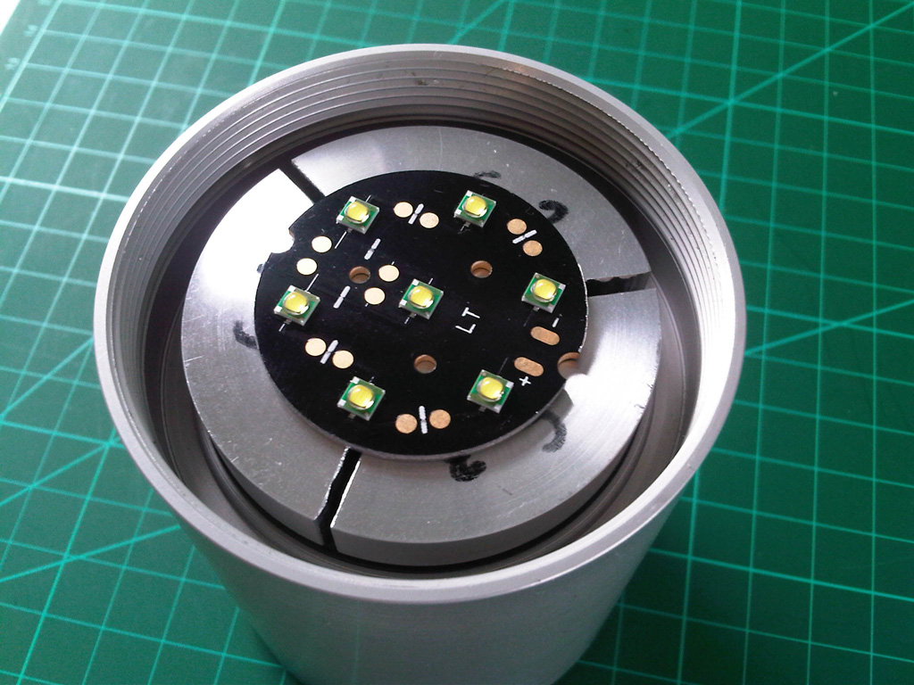
Good work ! - nice heat transfer , but middle led should be OFF , OR you have to put in middle cooper cork instead instead of that tube (same thing as Intel processor heatsinks .

Don't worry abour wires , you could drill hole somewhere between leds where is no Cu trace on AlPCB. Important at leds is that they have good thermal transfer in range of few milimeters from semiconductor joint ..... Al PCB also even more distribute heat equally but not to heat neighbours leds.

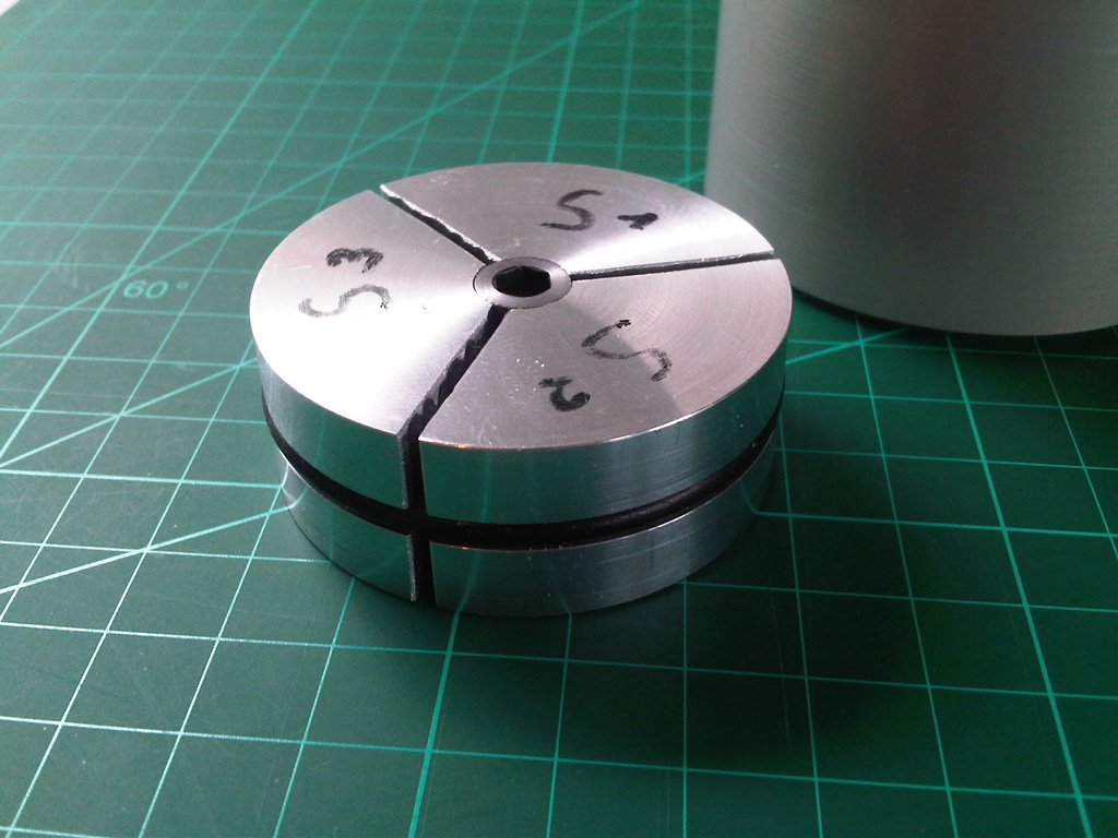
When wou made next time heatsink like that ...it is very good design , but you don't need to cut segments through , enough is only 1/2 - 2/3 max of cylinder only to transfer and distribute heat equally . Be sure that heatsink is inverted U hollow shape not full . (you don't want to collect and store heat in mass (Q=m*cp*dT ; A=Q*t)
------------------------------------------------------------------------------------------------------
OOT : (I work with some very special welding machines (hot stacking ) these days at work , I'll put energy of 2500W @ 1000A @ 55ms (constant power mode) in segments with cca 1g turned with enlameted wire 0,22mm (1turn/2turn ) whole thing have diameter 15mm and high 6mm with 6 these segments.
(carbon commutators - that on picture is big and heavy one :)
Auto-Kraftstoffpumpen-3Kohlekommutatoren.718899.jpg
Point of that is that with special approach it is possible to transfer pretty quick .
 
Last edited:

patrickDM

Newly Enlightened
Joined
Sep 15, 2009
Messages
18
Hi Lucca,

Thanks for your comments ... There's indeed plenty of room in the heatsink next to the outer diameter of the led-assembly to put the wires though ...
Putting a copper-slug in the hex-nut once tightened is a good idea, I'll give it a try ... for sure, the heat-transfer won't be ideal, but I guess better
something than nothing.
The inverted U-shape is indeed a good idea as well .... it would make a simpler construction, although some practical issues need to be solved .. i.e.
a conical hex which pushes out the "leaves" (to ensure tight fit) ends up in the bottom of the head ... which means you can't reach it normally .....
unless you make a hole in the top again, and this is to be avoided.

Cheers Patrick
 

lucca brassi

Enlightened
Joined
Feb 1, 2008
Messages
889
Location
US
a conical hex which pushes out the "leaves" (to ensure tight fit) ends up in the bottom of the head ... which means you can't reach it normally .....
unless you make a hole in the top again, and this is to be avoided.

Understand...
 

patrickDM

Newly Enlightened
Joined
Sep 15, 2009
Messages
18
Hi All,

Quick update on the head ... This is how I assembled the internals (sorry for the bad picture) ...

DiveLightInternals.jpg


As suggested, I disabled the inner led of the 7-xpg assembly, and as far as I can tell, the HS does a good job in transferring the energy to the housing ...

For the moment I have some issues with the MaxFlex powering-off the leds by itself ... I think this might be caused by noise being picked-up by the piezo-wires (despite
the 100nF cap below the red connector ... I now placed a second 100nF right at the MaxFlex trigger input as well, I hope this will fix the issue ...

Cheers Patrick
 

betti154

Enlightened
Joined
Jul 7, 2011
Messages
229
Hi All,

Quick update on the head ... This is how I assembled the internals (sorry for the bad picture) ...

DiveLightInternals.jpg


As suggested, I disabled the inner led of the 7-xpg assembly, and as far as I can tell, the HS does a good job in transferring the energy to the housing ...

For the moment I have some issues with the MaxFlex powering-off the leds by itself ... I think this might be caused by noise being picked-up by the piezo-wires (despite
the 100nF cap below the red connector ... I now placed a second 100nF right at the MaxFlex trigger input as well, I hope this will fix the issue ...

Cheers Patrick

I had similar issus without a 100nf cap, but since installing them at or very near to the board I've had no problems.
 

Delphinus

Newly Enlightened
Joined
Oct 15, 2009
Messages
68
One recomendation seal the end of the cable with silicone, many lamps flood the head thru the cable after a canister flood.
 

patrickDM

Newly Enlightened
Joined
Sep 15, 2009
Messages
18
Hi,

Some pictures on the finished head ..

After putting a 100nF cap straight on the switch-input pins of the MAxFlex I no longer observed the autonomous switch-off reported
in the earlier posts ..

Hopefully I'll be able to include some underwater beam-shots next weekend ..

Cheers

Patrick

IMG00159-20120311-1206.jpg


IMG00161-20120311-1208.jpg
 

lucca brassi

Enlightened
Joined
Feb 1, 2008
Messages
889
Location
US
These lenses are touching the front glass? There should be no airgap between lens and front glass . I'll also made mask around lens to stop light scattering inside the housing.
 

patrickDM

Newly Enlightened
Joined
Sep 15, 2009
Messages
18
Hi Lucca ... thanks for your feedback ... What's the reason for avoiding an airgap ? Practically, having the lens touching the glass poses some issues as well ... I.e. compression of the o-ring at depth can put quite some force on the lens assembly etc.

Cheers Patrick
 
Top