You are using an out of date browser. It may not display this or other websites correctly.
You should upgrade or use an alternative browser.
You should upgrade or use an alternative browser.
Help building a LED flashlight
- Thread starter thumpergirl
- Start date

thumpergirl
Newly Enlightened
- Joined
- May 21, 2013
- Messages
- 53
Just out of idle curiosity, what is a thumpergirl?
Thumper = single cylinder motorcycle. I am an adventure rider and big advocate of 'less is more'. I own 2 thumpers right now, a BMWF650GS and Yammi WR250R, but single cylinder dual sport bikes.
thumpergirl
Newly Enlightened
- Joined
- May 21, 2013
- Messages
- 53
Back at it again. For a quick follow up, I built several lights with the MR16 driver and they worked great. Best solution so far is Solarforce L2M host (has threaded shaft that can be removed to make it smaller), XM-L2 neutral white drop-in with OP reflector, some textured adhesive to go on the lens for better flood, MR16 1x3W driver, and PG7 cable gland. I had no trouble with mine last year and had a couple other people using them that really liked them. I intend to someday document the process and make it public and easy(ish) for someone to build their own light if they choose. Until then, they have this forum.
I did read that I could make the driver more efficient by removing the bridge rectifier diode since the input will always be DC. The more efficient I can make these, the better. Can anyone point me to the bridge rectifier diode on the MR16 driver? I *think* I know what it is, but I sure don't want to assume and get it wrong.
**Update, I think this is also what controls the polarity, so maybe I don't want to do this after all. It is highly likely that the light will get plugged into a battery pack the wrong way at some point.
Last edited:
thumpergirl
Newly Enlightened
- Joined
- May 21, 2013
- Messages
- 53
I also have one other question. I've bought so many parts I can't keep track of what's what. How can I discern the MR16 1x1w, 1x3w, and 3x1w at a glance?
Last edited:
DIWdiver
Flashlight Enthusiast
Congratulations on your success with the lights! How'd you do in the race?
A bridge rectifier is an arrangement of 4 diodes. Sometimes they are 4 separate parts, sometimes they are in one package. If it's one package, it will have 4 pins. Two will go the AC input wires, two will go to the rest of the circuit. If it's separate parts, there will be 4 identical parts. Each will have some sort of mark at one end. This is the cathode, and the other end is the anode. The bridge will have two parts with cathodes connected (this is the + output), the other two will have anodes connected (the - output). One free anode and one cathode will be tied to each AC input.
Some drivers intended to be used with batteries have bridge rectifiers at the input, some have "reverse polarity protection", which is usually a single diode, and some have nothing. A driver meant for AC will almost certainly have a bridge rectifier.
You can convert a bridge rectifier to a "reverse polarity protection" configuration and get half the efficiency improvement of removing the bridge completely. With this, it will work one way and protect the driver but not work if power is backward.
Another possible improvement is to change to a diode or diodes with lower voltage drop. Silicon diodes drop 0.6-0.7V, while schottky diodes only drop 0.1-0.5 depending on the part selected and the current through it. In a bridge rectifier, two at a time are working, giving a voltage drop of 1.2-1.4V for the silicon types, which are most common.
If you are up to the challenge, there's an even better way using an FET. It's a 'reverse polarity protection' circuit, but can drop as little as a few millivolts.
I can't help with the drivers. Maybe if we had pictures?
thumpergirl
Newly Enlightened
- Joined
- May 21, 2013
- Messages
- 53
Hi there DIW! Race went well, 2nd in my category. Was hoping for a better time but, I had a much more 'eventful' race than anticipated. This is probably going to sound like fiction, but it's not. My rudder bent early in the race, my rudder cable broke, my bilge switch died, I had a run-in with a mystery creature in the river that bit my leg/butt and ended up with a large infection, either a gator or a 200lb catfish knocked me out of the boat near the bay, had a run-in with a coatimundi while stuck on spoil island in the bay whole stole some of my belongings (wish I was making this up because I really needed that emergency blanket), and a shark passed me near the finish and it scared the $*** out of me. BAM. Gearing up to do it again this June, hopefully far less eventful this year.
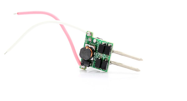
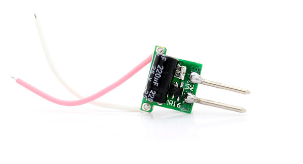
Am posting pics of the 1x3W MR16. Would love to know all the parts and components and how to make it more efficient. Have no idea how anyone would work on a such a small board, but I suppose it can be done? Polarity protection is fairly important, efficiency is very important, and size is also very important. The MR16 barely fits into the p60 host. I'm willing to switch up hosts, but without purchasing a ton of them and trying to disassemble them to see if they'll work, I'm at a loss for what to get.
Main goal is still to have a very small, compact, lightweight waterproof light, highly efficient so longer battery life, less heat so less housing necessary, and somewhere around 300-400 lumens.
I digress, back to the driver... I would love to understand and know how to do all the driver improvements you listed above. Cost and time are a consideration as well. I've heard of the schottky diodes before, but that's about as far as my knowledge goes. I'd also like to know more about the FET. Keep in mind, all of these would need to be small and I need to be able to fit them in a P60 host (unless I can go even smaller or somebody has a better idea that is cost effective). So, if a mod can't meet that spec then I'll probably need to come up with something else.
If you can look at the driver pics, help me identify the parts, and recommend improvements that fit the criteria, that would be awesome.
Can't thank you enough for your help. I really enjoy learning about this stuff and building these lights. Another addiction...") I'll post up a couple pictures of the lights I've built so far in another post. Hoping this thread helps someone else out who is trying to do this.
I'll post up a couple pictures of the lights I've built so far in another post. Hoping this thread helps someone else out who is trying to do this.
Am posting pics of the 1x3W MR16. Would love to know all the parts and components and how to make it more efficient. Have no idea how anyone would work on a such a small board, but I suppose it can be done? Polarity protection is fairly important, efficiency is very important, and size is also very important. The MR16 barely fits into the p60 host. I'm willing to switch up hosts, but without purchasing a ton of them and trying to disassemble them to see if they'll work, I'm at a loss for what to get.
Main goal is still to have a very small, compact, lightweight waterproof light, highly efficient so longer battery life, less heat so less housing necessary, and somewhere around 300-400 lumens.
I digress, back to the driver... I would love to understand and know how to do all the driver improvements you listed above. Cost and time are a consideration as well. I've heard of the schottky diodes before, but that's about as far as my knowledge goes. I'd also like to know more about the FET. Keep in mind, all of these would need to be small and I need to be able to fit them in a P60 host (unless I can go even smaller or somebody has a better idea that is cost effective). So, if a mod can't meet that spec then I'll probably need to come up with something else.
If you can look at the driver pics, help me identify the parts, and recommend improvements that fit the criteria, that would be awesome.
Can't thank you enough for your help. I really enjoy learning about this stuff and building these lights. Another addiction...
I'll post up a couple pictures of the lights I've built so far in another post. Hoping this thread helps someone else out who is trying to do this.
DIWdiver
Flashlight Enthusiast
You know, the Chinese have a saying, "may you lead an interesting life". It's not a blessing, it's a curse.
Sounds like a good race to have in the history books. You certainly won't have a lack of stories to tell!
Anyway, just google "FET polarity protection", then click on the 'images for fet polarity protection' link, and you'll see gobs of descriptions of how to do it. The bridge rectifier in your pics is comprised of the 4 black blocks next to the pins on the upper image. Replacing them with one of these http://www.digikey.com/product-detail/en/NTD4906N-35G/NTD4906N-35GOS-ND/2194521 would boost the driver efficiency by 8-9%. If you ensure your battery voltage never exceeds 20V, you can use the simplest of the circuits you'll find (just battery, FET, and load).
This will provide reverse battery protection (not reverse battery operation like you have now) with virtually no voltage drop - something on the order of 0.002V.
thumpergirl
Newly Enlightened
- Joined
- May 21, 2013
- Messages
- 53
So, I googled "FET polarity protection" and a bunch of foreign languages appeared (aka circuit diagrams?). I'll keep studying.
Reverse battery protection is great, I don't need reverse battery operation but I don't want to destroy a light if it's plugged into a battery pack that is incorrectly wired. So if it doesn't turn on, that's fine, just don't want to ruin anything.
So two things -
1) I do want to know how to modify the MR16 driver with the FET. So the bridge rectifiers are the 4 black blocks. I can just remove them without any special tools? They are sooo tiny. I suppose I'll need a different tip for my solder iron, and some tweezers for this? Solder paste? So I replace the 4 blocks with 1 FET (from here: http://www.digikey.com/product-detail/en/NTD4906N-35G/NTD4906N-35GOS-ND/2194521). Can you tell me, exactly, do I solder this? I've removed 4 chips and am adding 1.
2) Also, I would like more information about the simple circuit you talked about (battery, FET, and load). We can always assume under 20V (My battery packs will never exceed 18V. They are always 10 lithium AA batteries, never exceeding 19V), always DC power, and need reverse battery protection. So the most efficient way to build that in a tiny package less than 17mm (inside diameter of host). Would that be starting with the MR16 board and modifying it? I love the idea of little voltage drop.
DIWdiver
Flashlight Enthusiast
Each of those 4 parts individually is a a diode (aka rectifier). A bridge rectifier is the combination of 4 of them in a specific configuration to turn AC into DC.
If the board you have barely fits, then the best way is probably to modify it. There aren't many drivers around that small, especially ones that can handle 19V.
Yes, you'll unsolder those 4 parts and replace with the new one. You probably don't need a new tip, and you definitely don't need paste. The tools I like are solder wick (which is a strip of braided copper that will soak up the solder) and a dental pick. At work I usually keep a 1/8" tip on my iron, and I solder much smaller stuff than that.
I first wick off most of the solder (place wick on the solder, then the iron on the wick. You'll see when the solder starts to vanish). Then use the dental pick to put just a tiny bit of force to pry off the part, and hit it with the iron again. Because the terminals at the end of those parts are flexible, you can lift one end at a time.
The only things to be careful of are using too much force or keeping the heat on too long. Either can cause the metal foil to separate from the fiberglass backing. If you can, it would be good to practice on a board you don't care much about!
So in the circuit you are going to build you will have a battery , an FET, and a load. The first two are pretty obvious, the load consists of the driver and the LED. To be more specific, it will be what's left of the driver after you remove the bridge rectifier. Before you remove the diodes, you want to see how they are connected. Two of them will be connected at the cathode (the end with the whitish band across it). This will be the positive (+) side of the load. The other two will be connected at the anode side (opposite the cathode). This will be the negative (-) side of the load. The two input pins will each connect to one anode and one cathode. One pin will become your +battery connection and one will become your -battery connection. Probably best to determine this by playing around to see how the FET will connect most neatly.
You want to connect together the +battery pin, the +load connection, and the FET Gate (G). Then you want to connect the FET Source (S) to the -load connection, and the FET Drain (D) to the -battery pin. That's it!
Keep in mind that the big metal tab on the transistor is connected to the center pin, so you'll need to make sure it doesn't contact anything it shouldn't. A wrap or two of electrical tape should suffice.
thumpergirl
Newly Enlightened
- Joined
- May 21, 2013
- Messages
- 53
More questions!
These lights are working well, but I'm not a fan of the slow dimming effect. Is there a way I can add a voltage regulator to this circuit to improve the dimming issue? I would like the LED's to get a constant voltage until the batteries are too low to function, instead of dimming. The voltage regulator would need to fit into a host with an 18mm inside diameter. I also need to understand how to hook it up to the MR16 driver and battery.
There are two configurations:
#1) 1x5W MR16 driver feeding a single XP-L LED,
#2) and the second configuration is a triple XP-G2 wired in series, driven by an MR16 3x3W driver.
Mouser Electronics seems to have what I need, although I'm not sure exactly why to buy and how to put it together. Here is an example of what I think I need:
http://www.mouser.com/Search/ProductDetail.aspx?qs=QRsLLuHQazCCdYrl%2bmPkLQ==
Each one has a different output voltage and different output current. How do I know which one I need?
I'd like each of the lights above to run around 400 lumens, plus or minus.
The XP-G2 triple is an S4. At 350mA, it's lumens are around 186-195 (according to http://flashlightwiki.com/)
If each ran at about 350mA, the lumen output would approximately be 186-196 X 3 lumens, or between 558 and 588 lumens.
Is the following correct? :
If each LED in the triple were driven at 350mA, and they were wired in series, then I would need a 3x1W MR16 driver - each LED gets it's own 350mA.
If each LED in the triple were driven at 350mA, and they were wired in parallel, then I would need a 3X3W MR16 driver - all LED's share ~1000mA or 1amp.
The single XP-L V6 could be driven by a 1X5W MR16 driver to deliver around 500 lumens.
Assuming that is correct:
A) How do I know which voltage regulator to buy? Which is the correct output voltage and output current and why?
B) How is it wired in the circuit? Is it is wired between the driver and battery, or the driver and LEDs?
Of note:
- the battery pack that is driving this light is 10AA lithium batteries, outputting 18V when fresh.
- this circuit needs to be as efficient as possible. Battery life is important and needs to be at least 9 hours run time. More is better.
*** OR *** does the MR16 driver already have a voltage regulator on it, and if so, why is the light dimming? I'm not able to look at the parts and know what they are yet. MR16 pics in post above this.
Thanks CPF! (and DIWDiver for all of your help to this point!)
Last edited:
I'm glad DIW can help you TG, because I was lost several months ago.
DIWdiver
Flashlight Enthusiast
Maybe it's time for a crash course in regulator types and what they do.
Think about what the 'ideal' battery would be. It would have a fixed voltage, and would give you however much current you ask of it. Say you have an ideal 3V battery and a handful of 3V light bulbs, each of which draws 1A at 3V. Put one across the battery, and it draws 1A. Add another one in parallel (so it's directly across the battery too), and it will also draw 1A. The battery would now be supplying 2A, half of which goes to each bulb.
Now say you have a real battery, which is about 4V under load when fully charged, and about 3V when nearly discharged. This is pretty much what a lithium ion battery does. If you want to run the bulbs at a constant 3V, you need a voltage regulator. This will take the variable voltage from the battery and turn it into a fixed voltage. Like the ideal battery, its output is a fixed voltage at whatever current the load requires.
But say you had LEDs instead of light bulbs. Unlike light bulbs, LEDs don't do predictable things at specific voltages. If you buy a "3V" LED and put it on a 3V voltage regulator, it will likely NOT draw it's rated current, but something slightly or substantially higher or lower, and this would affect the light output, heat generation, and lifetime of the LED. You might find that to get it to draw the rated current, you need to supply one with 3.1V, and another with 2.9V. It gets even worse, because as an LED heats up, the required voltage drops!
So what's to be done? We want a current regulator instead of a voltage regulator. The ideal current regulator would put out a fixed current at whatever voltage the load requires. Set it for 350 mA and put that same 3.1V LED across it, it will draw exactly 350 mA at 3.1V. As the LED heats up, the current would stay the same as the voltage drops. In fact if you put the two LEDs in series across the output, you would get the required 6V at 350 mA.
Now obviously real regulators have limits. A 350 mA current regulator will have an output voltage range, say 2.5-8.0V. This can easily handle one or two of almost any white LED. Say you put your XPL across it. It will draw 350 mA, and the voltage will probably be a bit below the XPL's rated voltage, because the current is rather low for an XPL. Put an XPG across it, and the current will be the same, the voltage will be a little higher. But now say you put that triple XPG in series across it. The LEDs would want around 10V, but that's beyond the regulator's range and you will not get the desired result. Say you put a 2.0V LED across it. Some red LEDs are this low. Again it's outside the regulator's range and you will not get the desired result.
So in most cases, a good LED driver is actually a current regulator. Sometimes they are adjustable, and there are different ways of doing this, and there are other bells and whistles, but at their heart they should all be current regulators.
So why do your lights have this dimming problem? Because the current regulators aren't very good at their job. As the input voltage changes, the output current changes. This is common in very inexpensive switching regulators. The drivers you have are 'buck' type switching regulators. This is quite a common driver type for use in flashlights. It allows for converting a higher battery voltage to a lower LED voltage at high efficiency. Done well, it's capable of >90% efficiency, and rock-steady output to the bitter end of battery life. Done poorly, well you've seen that.
So there are two possible solutions to your problem. One is to have not an additional regulator, but just a better one. You'd probably get a bit (or maybe quite a bit) better efficiency and much better output regulation.
This may or may not be easy to do. I'm not much of an expert on what's available for purchase to fit a particular light.
The other possible solution is to add a voltage regulator in front of your current regulator (driver). If you supply your driver with a constant voltage, it will have a constant output. This is kind of a band-aid approach though, as it will add additional losses thus decreasing overall efficiency and it will also restrict the input voltage range by raising the minimum battery voltage required for proper regulation. The latter may not be a concern for you given the parts you are using.
Would it be possible to add a voltage regulator in the battery pack? There are lots of cheap buck type voltage regulators available, but I really doubt you'll find one to fit in an 18mm tube.
This post is getting pretty long, so maybe we should discuss choosing regulators later.