• You must be a Supporting Member to participate in the Candle Power Forums Marketplace.

    You can become a Supporting Member.

HOW-TOs, TIPS-and-TRICKS, DEFINITIONS, EXPERIENCES

Entropy

Enlightened
Joined
Dec 30, 2002
Messages
413
Location
Bridgewater, NJ
Re: HOW-TOs, TIPS-and-TRICKS, DEFINITIONS, EXPERIE

[ QUOTE ]
ChuckDecker said:
What is the meaning of "front voltage" (Vf)?

Does the word "front" refer to a physical location on the converter board or LED, or is this just the new term for voltage?

Thanks,

Chuck

[/ QUOTE ]
Vf is one of the specifications of the LED. I think it means "forward voltage", but the more specific definition is the forward voltage at which the LED will be operating at its rated current. For example, if a Luxeon has a 3.6v Vf, it will consume 350 mA at 3.6v. (Note: Even .1 volt above this and it will consume a LOT more, which is why LEDs are best driven with a constant current circuit.)

Vin is the input voltage to the converter. In step-up designs like the BadBoy and MadMax, Vf should ALWAYS be greater than Vin. If Vin exceeds Vf of the LED plus Vf of the diode in the converter (Usually this is between .2 and .6 volts), the converter no longer does anything and the LED is being directly driven from the input voltage.

I'm not sure, but I BELIEVE that the Wizard boards are flyback converters, which allow them to operate with Vin both above and below Vf.
 

LightChucker

Enlightened
Joined
Jun 5, 2003
Messages
617
Location
Raytown, Missouri USA
Re: HOW-TOs, TIPS-and-TRICKS, DEFINITIONS, EXPERIE

Andy, I really appreciate this explanation - very well written.

[ QUOTE ]
If Vin exceeds Vf of the LED plus Vf of the diode in the converter (Usually this is between .2 and .6 volts), the converter no longer does anything and the LED is being directly driven from the input voltage.


[/ QUOTE ]

I just ordered a BB500 and R2H and Q4H from the Shoppe. Both of the LEDs are rated at Vf 3.03 - 3.27. The BB500 is rated at Vin 1.6 - 9v with 500ma. Is this OK? It looks like that with a fresh 123 battery, the voltage will be almost perfect for the LEDs. What happens if I were to use 2 or 3 batteries?

Thanks,

Chuck
 

kakster

Flashlight Enthusiast
Joined
Feb 6, 2003
Messages
1,903
Location
London, UK
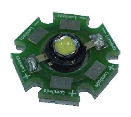
The easiest way to tell is if you get the LED still on the star PCB (this is how my R2H and Q4H came), you can just look at the solder pads, as they are marked with either neg. or pos. If you have just the emitter, look at the tabs next to the leads. I think the tab with a hole in is the positive side.
In answer to your previous post, i think the badboy is a step-up/boost only....if the voltage in goes above a certain level , it goes into bypass mode. Im not sure what the max voltage-in is, but im fairly certain that you can only use 1 cell max with the BB/1 watt LS combo.
 

AB0WA

Newly Enlightened
Joined
Apr 29, 2003
Messages
9
Location
Missouri
Chuck,

According to the LS emitter data sheet, there is a small metal tab WITH A HOLE OR SLOT IN IT, on the Anode side of the part.

By the way, nice to see a fellow citizen of Raytown here!

-Eric
 

LightChucker

Enlightened
Joined
Jun 5, 2003
Messages
617
Location
Raytown, Missouri USA
Hi Eric. How 'bout that - neighbors!

I'm thinking I may have bought the wrong thing. This Q4H LED is on a funny looking plate. It doesn't look anything like the instructions for the McLux. Can anybody explain that?

Thanks,

Chuck
 

kakster

Flashlight Enthusiast
Joined
Feb 6, 2003
Messages
1,903
Location
London, UK
Chuck, thats the star PCB that the LEDs are shipped on. you will need to remove the emitter from the board to put it in the mclux.
 

LukeK

Enlightened
Joined
May 30, 2003
Messages
529
Location
TX
Simple directions for removing emitter:

(I've done it twice and I'm new at this, so don't worry -- it's easy!)

Heat up your soldering slightly and hold it to the bottom of the Luxeon Star (the aluminum sheet on bottom) until it is warm to the touch. It doesn't need to be hot, just warm. There are two copper tabs attached to the emitter that are soldered to the 'star' board. Hold your desoldering iron onto one of the copper tabs and wait until you can see obvious liquid movement around the tab. Then very quickly, with a toothpick, gently pry the copper tab from it's resting place. Do not apply to much force, as you do not want to break the tab off. Repeat the technique with the other end of the emitter. Note: Keep track of which end is positive and which end is negative before you take the emitter off. Continuing on, grab two pairs of pliers. Firmly grip the 'star' on each side of the emitter and twist slightly. The emitter should either pop right off, or you will be able to simply pick it up from it's resting place with your fingers. Good luck! (Oh -- and keep the soldering iron away from the dome of the luxeon heh!)

[Edit] Just to make sure, your Luxeon does look like the one in the following picture correct?

Luxeon_Star_5W.1.jpg


(The picture used is from the Elektrolumens site)
[/edit]
 

dat2zip

Flashlight Enthusiast
Joined
Jan 5, 2002
Messages
3,420
Location
Bay Area
I would suggest an alternative and more safer way to remove the emitter. Heating the whole aluminum to the soldering melting point is ~600F. That also means the slug and thuse the die get to that temperature. Lumileds states that exceeding the 120C (248F) will likely damage the LED. What gets damaged and how I don't know.

There are very detailed instructions on how to solder the Emitter down without exposing the package and LED to improper temperatures.

Thus, I recommend the following. Solder wick off the leads till they have very little solder on them. Heat them up and witn a small tool/exacto knife/toothpick pry the LED lead up till it is free. Do this for both ends.

On the back side score a groove with a file or dremel down the middle parallel to the LED leads.

Now with a vice or two pliers bend downward the aluminum disk. If you do this correctly the LED will get exposed and further bending will pop the LED off. I usually go far enough where I can see the bottom of the LED and use an exacto to finish the job.

Wayne
 

LukeK

Enlightened
Joined
May 30, 2003
Messages
529
Location
TX
Wayne --

Simply heating up the copper tab for a few seconds seems to be all that is required. Surely that incredibly short amount of time wouldn't damage the LED...right?
 

dat2zip

Flashlight Enthusiast
Joined
Jan 5, 2002
Messages
3,420
Location
Bay Area
LukeK,

Sorry, I misread your post. No, you are correct. Heating it slightly is not a problem. I misread it and thought you were heating from the bottom till the leads came unsoldered. My mistake. Sorry about that.

Wayne
 

tvodrd

*Flashaholic* ,
Joined
Dec 13, 2002
Messages
4,987
Location
Hawthorne, NV
If you want to use Wayne's electronics (boards)and a Luxeon Star, you can usually just clip the leads on the "Star" alum PCB. That leaves enough remaining on the emitter to solder to. You can then bend the aluminum "Star" board in a vise with a set of pliers to break the emitter loose (Do a search on the actual techniqe.) The 'tabs" adjacient to the actual diode leads appear to be electrically common to them in case they break! The headers Wayne supplies with his emitter boards and their associated holes are such that centering everything is pretty easy to do. ( /ubbthreads/images/graemlins/bowdown.gif /ubbthreads/images/graemlins/bowdown.gif Wayne)

Larry
 

LightChucker

Enlightened
Joined
Jun 5, 2003
Messages
617
Location
Raytown, Missouri USA
You guys have been GREAT! /ubbthreads/images/graemlins/bowdown.gif /ubbthreads/images/graemlins/bowdown.gif /ubbthreads/images/graemlins/bowdown.gif

I think I'll be OK now - at least to this point. I'm going to spend some time comparing the McLux instructions to the parts before doing anything. So, I'll probably have more questions.

Even if I wanted to get started today I couldn't, because SVC sent the wrong stuff, and they have not responded to any emails. I ordered the Arctic Alumina Epoxy, but they sent the compound instead. (See the Cheers and Jeers Forum.) I don't care if they are cheeper, I will pay more for more reliability.

Thanks again guys! I really appreciate your taking the time to write such good instructions (with pictures even).

Chuck
 

LightChucker

Enlightened
Joined
Jun 5, 2003
Messages
617
Location
Raytown, Missouri USA
I thought I would report on my progress to make my own McLux. You veterans might find this boring. But then, you might find it reminiscentof your own first adventures.

Using the tips from everyone, I successfully detached the LED from the aluminum plate. Of course, like you said, it was easy. It always is once you know how. It was just that I wasn't expecting to do any dis-assembly before I did a-ssembly.

I first clamped the unit to the bench. Then, I used a solder-wick to suck up the solder. Finally, for each tab, I used a pointed tool under the tab while applying some heat. The tabs lifted right up. The final move was to clamp one side of the plate in a needle nose Vise Grip, and tork it with another plier. The LED just fell off with very little effort.

Just to make sure all was well, I soldered some wires to each end of a spent battery, and touched the wires to the LED. I was careful to touch the positive lead from the battery to the side of the LED that had the square-holed tab. It glowed dimmly, letting me know that it had survived my first LEDectomy.

I have also drilled and tapped a new hole below each of the accessory ports on the switch guard. These are to receive a brass swivel button. I tapped two holes, because I find that turning the light on from the hip is easier for me when the pocket clip faces forward. That is different depending on which side of your body the light hangs from. So, this makes changing my mind later a little easier.

Another step that I took was to "break-in" the threads that join the battery tube to the bezel. It was VERY tight at first. It wouldn't even take a half turn before locking up. I did as one CPFer suggested and applied some Flitz to the threads. Then, I twisted the two together repeatedly for a few minutes. The result was a very smooth and easy fit.

Since then, I have ordered some Arctic Alumina Adhesive from the Shoppe. So, I'll have to wait till it arrives before I can really get serious.

I'll try to log another entry when I do the next step.

Chuck /ubbthreads/images/graemlins/wink2.gif /ubbthreads/images/graemlins/wink2.gif /ubbthreads/images/graemlins/wink2.gif
 

LukeK

Enlightened
Joined
May 30, 2003
Messages
529
Location
TX
Excellent! Glad to hear that the Luxeon surgery went well. I look forward to more updates, and possibly some pictures!
/ubbthreads/images/graemlins/thumbsup.gif
 

LightChucker

Enlightened
Joined
Jun 5, 2003
Messages
617
Location
Raytown, Missouri USA
Recommended solder and flux formulas?

/ubbthreads/images/graemlins/thinking.gif

I know how to solder, but it's been a while since doing electronic soldering. I used to use the liquid flux. (I think it is hydrocloric acid.)

Is that still OK these days?
Are there any solder or flux formulas to avoid?
Any to recommend?

Thanks for the help!

Chuck
 

tvodrd

*Flashaholic* ,
Joined
Dec 13, 2002
Messages
4,987
Location
Hawthorne, NV
Chuck,

Most of us use rosin core solder- the rosin flux is less corrosive than acid and is the recommended for electronic work. The rosin flux is inside the solder and thus "core." You should be able to get it it Radio Shack- get the thinnest they have. Also you will need a soldering "pencil" rather than an old fashioned "iron" or "gun" for fine work. When possible it is also a good idea to remove any remaining flux from the joint when you are done. Otherwise, it will eventually corrode over time.

Larry
 

Mednanu

Enlightened
Joined
Feb 16, 2003
Messages
333
Location
Earth...
While I'm sure that many brands out there will work just fine, I've had very good results with <font color="orange">Kester #44</font> rosin core solder in .031" diameter or smaller. It's a 60sn/40pb mix that I think is eutetic or very darn close to it (very little to no 'plastic state' while the solder cools - it goes from a liquid right to a solid state ). It's very nice solder and can be had for very economical prices on eBay. I think the ideal eutetic mix is arount 63sn/37pb, but they both work quite well. You may want to keep the size of the solder's diameter to .031 or LESS if you plan on working with small parts like Wayne's BB units or ARC flashlights. If you plan to work on larger direct driven rigs (like Maglights), you may wish to purchase .050" or larger diameter solder.
 

tvodrd

*Flashaholic* ,
Joined
Dec 13, 2002
Messages
4,987
Location
Hawthorne, NV
Mednanu,
The place I work decided Maintenance and my shop would convert to lead free solder. I saved them the hazmat disposal by taking home 3 1# rolls of Kester .031" Sn63Pb37.
/ubbthreads/images/graemlins/grin.gif /ubbthreads/images/graemlins/grin.gif

Larry
 

Mednanu

Enlightened
Joined
Feb 16, 2003
Messages
333
Location
Earth...
[ QUOTE ]
tvodrd said -
Mednanu,
The place I work decided Maintenance and my shop would convert to lead free solder. I saved them the hazmat disposal by taking home 3 1# rolls of Kester .031" Sn63Pb37.

[/ QUOTE ]

You lucky dog !!! /ubbthreads/images/graemlins/grin.gif
 
Top