its here !!!

PEU

Flashlight Enthusiast
Joined
Feb 26, 2004
Messages
3,600
Location
Buenos Aires / Argentina (I like ribs)
will said:
Are you sitting down? Are you ready to cringe?


I probably didn't spend $10,000 for tooling, This is probably less than $75.00. I can do pretty much anything with this modest set of tools. The hex keys are hardened and with a little grinding make great boring bars. The small one in the front can be used for face grooves or boring small diameter holes. The internal threading tool is solid carbide (front right)

I work mostly with wood or aluminum, so I don't need carbide bits, I use mainly tool steel and grind my own profiles.

I worked as a machinist and learned a lot about tool making and grinding, even hand sharpening drill bits.
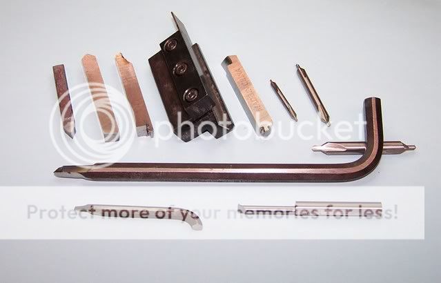

tools.jpg

Nice! nothing beats the experience!

The other day I went to the CNC shop that do my parts and instead of talking about stuff needed to be done, one of the machinists teached me how to properly sharp a tool, at least the fundamentals of it, it was a real eye opener. Of course this was AFTER I commited to a couple of carbide tool holders :ohgeez:

I didn't know allen wrenches could be used to make tools, thats interesting. But cobalt-steel blanks aren't that expensive, and I guess they keep the sharpness better.


Pablo
 

wquiles

Flashaholic
Joined
Jan 10, 2005
Messages
8,459
Location
Texas, USA, Earth
modamag said:
Will, congrats on the new toy/tool. I C you're trying to do the "correct" VFD. 2hp might be a little too much for the little guy. Heck even 1hp 220 AC is a bit much for him. But then again it's VFD.

As for your 4-Jaw adapter plate, it's not the same as the 7x12 TMK.
They're pretty easy to make if you have a face plate.
I have an extra one. I think :scratching head:
If you're interested drop me a PM.

If you still want to make it, let me know. I'll draw it up in couple days.

PM sent - thanks!

Will
 

wquiles

Flashaholic
Joined
Jan 10, 2005
Messages
8,459
Location
Texas, USA, Earth
OK, the process of getting the 8x12 to be Variable Speed started !!!

First I got a 110/220 DC controller, capable of up to 2 HP. I then got a new 180V TEFC Leeson motor of approx. 1HP - lets say that it is pretty "large" :) . True, I only needed about a "true" 1/2 HP or so, but there is no harm in having a little more powerful motor as I can control the power rating right at the new controller by selecting the appropriate HP power resistor (just a large wattage sense resistor). Here is the new motor box right in front of my 7x12 mini-lathe:
IMG_0301.JPG


IMG_0306.JPG


Here is the motor next to the OEM motor in the 8x14:
IMG_0309.JPG


Today I started the disassembly process - I mean, I have to figure out a way to put that large motor in the 8x12!:
IMG_0441.JPG


IMG_0442.JPG


IMG_0443.JPG


IMG_0445.JPG


IMG_0446.JPG


then take the "extra" pulley - which I should not need once I have variable speeds:
IMG_0453.JPG


then the motor is off:
IMG_0456.JPG


I don't know for sure until I try, but I am going to try to mount the new motor (somehow) to the same spot as the OEM motor:
IMG_0457.JPG


Since my new motor has a larger shaft diameter than the OEM unit, I am planning on boring the OEM pulley and re-using it. Even though I will have variable speeds, keeping the pulley should give me 2 or 3 speed ranges - that might come handy later on:
IMG_0459.JPG


IMG_0469.JPG


Here is a side by side comparison. Note that the "cheapy" motor is rated at 550 watts, but the Leeson is rated at 750 watts. The Leeson motor is simply built like a tank!:
IMG_0460.JPG


IMG_0461.JPG


and again without the face plate (which I am not going to use to mount the new motor):
IMG_0462.JPG


IMG_0463.JPG


IMG_0464.JPG


I checked the hole alignment in the OEM motor vs. the Leeson - no luck. At least it is not going to be plug and play easy :D
IMG_0465.JPG


IMG_0466.JPG


IMG_0467.JPG


Here is the "skeleton". Even without the motor and the extra pieces, it was so freaking heavy that I had to get my neighbor to help get it on top of the work bench - this thing is truly in a different league than my 7x12. Now my new lathe is ready to be cleaned, decreased, adjusted, etc.. Once I have all that done, I will then proceed to work on mounting the motor and wiring it to the new controller board. More fun to come!
IMG_0490.JPG


IMG_0492.JPG


Will
 
Last edited:

DonShock

Flashlight Enthusiast
Joined
Dec 28, 2005
Messages
1,641
Location
Belton Texas
Looking at that edge view of the two motor mounts, it would appear that you can remove the mount off the new motor. It looks like if you made the bends a little tighter, you could get it to be much closer to matching the width of the original motor mount. And then you could just drill an additional hole in the new mounts, the one to the right of the clamp in the picture, so that you could use the original tapped holes on the lathe.
 

kenster

Flashlight Enthusiast
Joined
Nov 6, 2005
Messages
2,095
Location
San Antonio, Texas
Will, you are having fun now! :party: The pics took quite a while for me to download with dialup but well worth the time. Great job! :twothumbs Well, so far anyway! ;) I really didn`t think you could get a 1HP in there but it sure looks like you are on the way to proving me wrong! :eek: I would be a happy camper if you would share some info on exactly what and where for the parts. And I suppose, how much would it damage my wallet to try this on my Lathe??? :broke: The mounting bracket appears to be a little wimpy compared to the other but pictures can be somewhat decieving to judge this???? :shrug: You still got some hurdles but looking good so far. You mentioned leaving the pulley for extra slow speeds. Have you seen the speed reduction pulley LatheMaster has for the 8 x 14? I ordered one with my Lathe. Might fit yours and it is a 50% reduction. Here is a link if you feel like checking it out.

http://lathemaster.com/osc/product_info.php?cPath=2&products_id=313

Please keep posting the updates for this project with plenty of pictures! :popcorn:

Ken
 

ICUDoc

Enlightened
Joined
Aug 20, 2004
Messages
907
Location
Sydney, Australia
I am envious -that all looks like a lot of fun.
Can you fabricate a whole new mounting bracket for the Leeson?
I have no experience but it looks removeable....
 

Anglepoise

Flashlight Enthusiast
Joined
Nov 4, 2004
Messages
1,554
Location
Pacific Northwest
Enjoyable reading. The motor is a life long investment and variable speed is the way to go. You will love it.

Like to see a pic of the controller when you have a minute.
 

will

Flashlight Enthusiast
Joined
Apr 14, 2004
Messages
2,597
Looking at that edge view of the two motor mounts, it would appear that you can remove the mount off the new motor. It looks like if you made the bends a little tighter, you could get it to be much closer to matching the width of the original motor mount. And then you could just drill an additional hole in the new mounts, the one to the right of the clamp in the picture, so that you could use the original tapped holes on the lathe.


I would remove the mount and re-bend it to fit - then drill 2 holes to match the tapped holes in the lathe.
 

wquiles

Flashaholic
Joined
Jan 10, 2005
Messages
8,459
Location
Texas, USA, Earth
Thank you guys for the suggestions and encouragement. I will be trying some of these shortly :twothumbs


I would be a happy camper if you would share some info on exactly what and where for the parts. And I suppose, how much would it damage my wallet to try this on my Lathe???
Motor: Brand new on Ebay: $49 + $22 s/h - talk about a "great" deal!. I waited for about 2-3 months until I found the right one at a great price ;)

Controller: KBMM Model 225D. Brand new on Ebay = $49 + $5 s/h. Same here, I searched for 3-4 months until I got one this cheap. Only thing to buy are two cheap fuses and a special (about $10) high power sense resistor to set the max. power in HP (or fractional HP). Here are photos of the actual controller (the two power ratings on the controller are for "as is", with no extra heat sink, and the higher range for when you have a larger, external heatsink, which is the direction I am headed regardless of the actual power usage - I am doing this one time, and I am doing it right, with extra margin!):
IMG_0509.JPG


IMG_0511.JPG


IMG_0514.JPG


As you can see here, if I do things right, I should be able to install the new controller in the same place as the OEM switches go. Plus if I do things "really" well, I will mount the new controller and use the metal housing as an extended heat sink along with an external, large heat sink so that the controller will run cooler (longer life) - remember that I want my setup to support up to a true 1 HP :grin2: . I am also considering having a small fan to cool the controller board just like the one my mini-mill has - that sounds like a simple and neat idea ;) :
IMG_0518.JPG


Have you seen the speed reduction pulley LatheMaster has for the 8 x 14? I ordered one with my Lathe. Might fit yours and it is a 50% reduction. Here is a link if you feel like checking it out.
It is nice if you have the fixed speeds as in the OEM setup, but in my setup there would be no practical need to mechanically cut everything in half when the variable speed motor/controller will give you infinite control.

To have "some" flexibility is why I am considering retaining the OEM pulley from the old motor - I can then by changing the belt position & tensioner change speed ranges depending on what I am doing. Still, with so much power in the new motor, even at a higher speed range, the new motor will still have massive amounts of torque at lower speeds, so the whole thing might be an overkill in flexibility. I am just doing it to have the flexibility even if I never need it :)

Will
 
Last edited:

will

Flashlight Enthusiast
Joined
Apr 14, 2004
Messages
2,597
OK - now the dumb question - Does your lathe have any plastic gears? Nylon gears? I will go out on a limb here - Most machines are made/designed with certain performance characteristics in mind. For example - a certain HP motor which will not tax all the gears and bearings in the lathe. Mine will start to stall if I am cutting too heavy, but nothing breaks. The stalling is like the warning track - slow down or take a smaller cut.

My Mini-lathe has variable speed - that is great to have, just change the dial and off you go. My drill press has a series of pulleys to change speeds - a pain in the neck.

Some years back I put a rather large engine in a car I was making into a street rod. - first to break - the original transmission, replaced with a heavy duty transmission, then the universals, then the axles - In short - I had to replace the entire drive train with something much heavier to take the extra power from the engine. I knew this going into the swap - so I was not surprised to break stuff..
 

modamag

Flashlight Enthusiast
Joined
Aug 16, 2004
Messages
2,101
Location
Bay Area, CA
will, these HF 8x12 are metal gears. The HF 7x14 (minilathe) are nylon gears.

There are quite a few guys who put a 1hp VFD on these. The gear seems to handle it fine. Now the part I see most problematic is the spindle. If you don't take deep cuts I think it's fine.
 

will

Flashlight Enthusiast
Joined
Apr 14, 2004
Messages
2,597
Mine has a series of nylon gears, there is a high/low speed lever which has a set of plastic gears ( these are the ones that PEU had to change ) Sometimes bigger is not always better. I would make the change just for the variable speed, that is just so much better.

The spindle? - or - the spindle bearings?
 

wquiles

Flashaholic
Joined
Jan 10, 2005
Messages
8,459
Location
Texas, USA, Earth
OK, I got some more work done yesterday, and I also got some new toys. As for the motor mount, I am finished. I was able to slightly bent the motor mount to fit in the 8x12 lathe, and I drilled 4 new wholes to match the motor mount:
IMG_1478.JPG


I got some grade 8 steel bolts/hardware ready, so the mounting of the motor has been accomplished :thumbsup: :
IMG_1479.JPG


Toy #1: Lathemaster, wedge-type, already-modified Quick Change Tool Post for the 8x12:
IMG_1480.JPG


Toy #2: Boring head for my mini-mill:
IMG_1468.JPG


which I quickly disassembled, cleaned, and lubed properly:
IMG_1466.JPG


I of course put it to good use to bore the pulley from the old motor to use with my new 1HP motor:
IMG_1469.JPG

IMG_1470.JPG

IMG_1471.JPG

IMG_1472.JPG


being that I am still a beginner I ended up a few mills larger than the target, but it should work well:
IMG_1473.JPG


Do you guys have some ideas to cut the key slot in the pulley? I am doing it by hand a little bit at a time, but needless to say it is a very sloooow process :hairpull: :
IMG_1476.JPG


Ideas/suggestions? :anyone:

Will
 

PEU

Flashlight Enthusiast
Joined
Feb 26, 2004
Messages
3,600
Location
Buenos Aires / Argentina (I like ribs)
My minilathe uses the same speed controller but in 220v version, its very nice.
Follow their tune up sequence and you will have great performance.
Over time I fixed it about 3 times, nothing difficult. If you search the web you will find the board schematics, at least I found them for my board.

There is a machine to do slots on gears, but it just automates the work you are doing by hand, so I cant give you a better advise...


Pablo
 

will

Flashlight Enthusiast
Joined
Apr 14, 2004
Messages
2,597
To cut a slot for a keyway you have to 'broach' it. Best bet is to look that up. We used to do it manually, basically it's a square tool bit we used to put in a milling machine. ( unplug the machine ) then you just start to put a slot in by ramming the square bit up and down. You have to move the work into the tool a few thousands at a time. You are more or less scratching in the keyway.

Also - for an oversized hole - sometimes you can shrink it a bit. Get a steel ball larger than the hole - 1 1/2 -2 times the size of the hole. Smack it with a hammer, do both sides. what happens is that you are pressing the metal in. I don't think you will find that written up anywhere.
 
Last edited:

gadget_lover

Flashaholic
Joined
Oct 7, 2003
Messages
7,148
Location
Near Silicon Valley (too near)
Broaching is often done with a press to push the broach through the piece. Some very complex holes are made by broaching. The hole in the lock that the key goes into is made by broaching.

You can buy broach sets for woodruff keys. One that looked interesting had a stepped cutter (about 8 inches long), a round insert to fit the hole in the gear (with a keyway) sized slot, and a set of spacers the same width as the broach.

To use it you pop the insert into the hole, run the broach through the whole length (gouging a groove a few thousandths deep) , then put in an insert to push the broach further out and start again. A few passes and you have a nice consistent keyway.

I've thought about building a set for my own use, but have not gotten around to it.

I found a link to broach sets if you want to see how what I'm talking about.

http://www.jtsmach.com/jtswebshop/Pr_CuttingTools/BR021.asp#10


Daniel
 

Anglepoise

Flashlight Enthusiast
Joined
Nov 4, 2004
Messages
1,554
Location
Pacific Northwest
One possibility is to use your lathe like a shaper.
Grip the pulley in your chuck,
Get your new toolpost set up and then custom make a tool.

The idea is to hold the pulley stationary, and have the tool move left and right down the length of the carriage. If you take very small cuts and your tool is sharp, you will be surprised how quickly it goes.
 
Top