It appears you can't really turn U2 off. Even when Q1 is off, there is a path from VccIN through R6, through U2 to Vdd, thence through R15 and Q4 to Pgnd. The total impedance is 800 ohms plus a diode (Vbe) drop, which is not enough to keep U2 reliably shut down.
Can you explain how the piezo works? I'm not seeing it. The piezo switches I have seen are momentary contact closure (momentary FET turn on, actually), and in this circuit it looks to me like it could turn the power on but not off. What am I missing? Once the circuit is on, how does it turn off?
D
Okay, so you have me interested.
I started thinking about how you could make a circuit to turn a load on and off using a single piezo switch. The problem is that piezo switches can only be closed for a brief time (a few milliseconds to a few tens of milliseconds). I found that it could actually be done with a handful of components that anyone with a little soldering skills could assemble. The other interesting thing is that the circuit I came up with is remarkably similar to the one you posted.
I think the circuit as you posted it has a mistake or two in it, but I'm still not seeing exactly how it's supposed to work, and so can't find the mistake. Maybe someone more observant than me can find it!
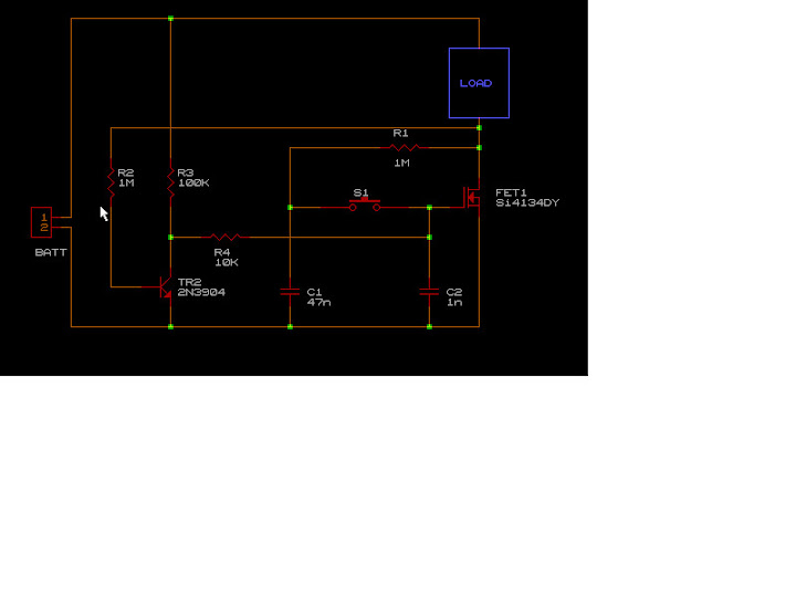
In the meantime, I came up with a circuit that I think should work. It's a bit simpler, and has the advantage (for me) that I can understand it.
Here's how it works: The piezo switch (SW1) is open most of the time, and can only be closed for a short time, because of the nature of the switch. No matter how you press it, it will close briefly, then open. Thus we can look at the circuit with SW1 open. The circuit will be either 'on' or 'off'. I consider it 'on' if FET1 is turned on and there is power applied to the load.
When the circuit is on, the voltage at the drain of FET1 is near zero, and C1 will discharge through R1 and FET1. Also, TR2 will be off, because there is no base current through R2. Since TR2 is off, R3 and R4 will pull the gate of FET1 high, which will turn it on. Thus this state is stable (meaning it will stay this way forever, unless something changes).
When SW1 is pressed, several things happen in a very short amount of time. C2 is discharged through SW1 into C1. This pulls down the gate of FET1 and turns it off. The load pulls the drain of FET1 high. This turns on TR2 through R2. TR2 pulls the gate of FET1 low through R4. This keeps FET1 off.
Once this state is reached, it is also stable, regardless of the status of SW1. As long as SW1 is closed, C1 is being discharged through R4 and TR2.
Once SW1 opens, C1 is charged through the load and R1. When SW1 is closed again, FET1 is turned on by the voltage charge on C1. Once FET1 is on, the load is turned on and R2 is pulled low, which turns off TR2. This allows the gate of FET1, to be pulled high by R3 and R4. Again, this state is stable.
What do you think guys, will this work?

")