looking for PWM controlled constant current component

jspeybro

Enlightened
Joined
Aug 13, 2009
Messages
586
Location
Belgium
Hi,

difficult to put a clear title, but this is what I'm looking for:
A driver chip for high power LEDs that is constant current, and where the output current can be controlled using a PWM signal while the output is not a PWM output.
So, I'd like to use a PWM signal to control the output current instead of what is done usally,run LED at full power and pulse the LED to dim the overall averaged output).
This would mean that by changing the duty cycle, one would change the actual current to the LED.

Is anyone aware of such a driver chip?
I'm looking for controlling currents in the 100mA-1000mA range more or less but anything that comes close is probably a good start.

Thanks,
Johan
 

hiuintahs

Flashlight Enthusiast
Joined
Sep 12, 2006
Messages
1,840
Location
Utah
...........I'm looking for:
A driver chip for high power LEDs that is constant current, and where the output current can be controlled using a PWM signal while the output is not a PWM output.
So, I'd like to use a PWM signal to control the output current instead of what is done usally,run LED at full power and pulse the LED to dim the overall averaged output).
This would mean that by changing the duty cycle, one would change the actual current to the LED.

Is anyone aware of such a driver chip?............
Thanks,
Johan
I'm sure there are several types of these PWM chips out there but I can't put my finger on an exact one without doing some research.
Go to Onsemi.com website and put "pwm LED driver" in their search bar. I saw quite a few come up.
I think you could do that also for Ti.com and the other semiconductor companies.

I know you are in Europe but the other thing you can do is go to an electronics supply like Mouser or Digikey here in the states and see whats available. Maybe you could go to Farnell / Newark website which is in Europe.
 

jspeybro

Enlightened
Joined
Aug 13, 2009
Messages
586
Location
Belgium
don't worry about sourcing. mouser, digikey, RS compentens, Farnell etc are available to me.

The problem is that when I search on PMW led drivers, I'm getting drivers that have a PWM output, which is not what I want. All drivers that I see use a resistor to set the current and dim the LED by PWM, so they pulse the LED with a certain frequency and duty cycle to reduce the overall brightness.
I want to use the duty cycle of the PWM to replace that sense resistor.
 

sunny_nites

Enlightened
Joined
Mar 27, 2010
Messages
491
Location
USA
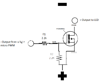
Basically, I use a P-channel mosfet (P-channel because the output from the X-Light Micro is negative) to drive LEDs at higher current from a X-Light Micro PWM circuit. That way I can run say, a XP-G at 1.2 amps from a circuit that was designed to run a 5MM LED at 60 mah.

This is the circuit I use:
396d560b-17b0-4a25-8e9a-dade87503fde_zpsb71ed100.png

I generally don't change the value of R1 but I can increase or decrease the maximum current output by changing R2. Might seem counterintuitive but a larger value for R2 will increase the current output, while a lower value for R2 will decrease the maximum current.

The values above are drving a XR-E (just what I happened to have setup on my bench) up to approximately 1.2 amps.

I'll have to do some searching for the part# for the mosfet if you would like it, I bought a bunch of them years ago and don't recall it off the top of my head but it is a typical 1.8V mosfet rated for 1.4 amps. There have probably been advances since I purchased mine and likely the newer ones can handle much more current though.
 
Last edited:

hiuintahs

Flashlight Enthusiast
Joined
Sep 12, 2006
Messages
1,840
Location
Utah
don't worry about sourcing. mouser, digikey, RS compentens, Farnell etc are available to me.

The problem is that when I search on PMW led drivers, I'm getting drivers that have a PWM output, which is not what I want. All drivers that I see use a resistor to set the current and dim the LED by PWM, so they pulse the LED with a certain frequency and duty cycle to reduce the overall brightness.
I want to use the duty cycle of the PWM to replace that sense resistor.
OK, so you don't want a PWM current driver just the mechanism that controls the current to be PWM. I'm not sure of any driver IC's that work that way........not that there isn't just that most that I've seen use a voltage feedback to regulate things. I know you can come up with a PWM signal that is variable by using a 555 timer or an LM3524, but I think there are easier ways to accomplish dimming.

The typical method for current regulation on a switching type driver is to place a small resistor in series with the LED current which will translate the current to a voltage that then is fed back to the FB pin of the driver IC. Most of these FB pin voltages are around 1.25v and so if you're wanting 1 amp of current, then a 1.25 ohm resistor is needed. Well 1.25v is a pretty big ratio of the Vf across the LED and that wastes a lot of power. So what I do is place a very small resistor like 0.1 ohm or smaller, and then use an op-amp gain stage to bring the voltage up to 1.25v..........or whatever it is on the driver IC being used. If you do it that way, you can replace one of the resistors around the op-amp with a potentiometer and that will allow you to have a range in output based on the values of resistors and pot used.

I guess I'm not quite understanding why you want to use PWM to dim the LED or what the advantages of it are.........because to me it seems to be more parts involved? I think there is a little confusion of terms here. If you want a "constant current" driver as you mentioned in the first post, then it will not be a PWM'ed output. However all switching type of drivers use PWM internally for regulation, but you won't be messing with that as its part of the stability feedback loop internal to the IC and compensated externally. All these types of drivers use a voltage controlled feedback input. So it makes no sense to me to use PWM with those type of regulators.

Straighten me out otherwise...........just trying to help out the best I can.
 
Last edited:

StandardBattery

Flashlight Enthusiast
Joined
Sep 2, 2007
Messages
2,959
Location
MA

jspeybro

Enlightened
Joined
Aug 13, 2009
Messages
586
Location
Belgium
OK, so you don't want a PWM current driver just the mechanism that controls the current to be PWM. I'm not sure of any driver IC's that work that way........not that there isn't just that most that I've seen use a voltage feedback to regulate things. I know you can come up with a PWM signal that is variable by using a 555 timer or an LM3524, but I think there are easier ways to accomplish dimming.

The typical method for current regulation on a switching type driver is to place a small resistor in series with the LED current which will translate the current to a voltage that then is fed back to the FB pin of the driver IC. Most of these FB pin voltages are around 1.25v and so if you're wanting 1 amp of current, then a 1.25 ohm resistor is needed. Well 1.25v is a pretty big ratio of the Vf across the LED and that wastes a lot of power. So what I do is place a very small resistor like 0.1 ohm or smaller, and then use an op-amp gain stage to bring the voltage up to 1.25v..........or whatever it is on the driver IC being used. If you do it that way, you can replace one of the resistors around the op-amp with a potentiometer and that will allow you to have a range in output based on the values of resistors and pot used.

I guess I'm not quite understanding why you want to use PWM to dim the LED or what the advantages of it are.........because to me it seems to be more parts involved? I think there is a little confusion of terms here. If you want a "constant current" driver as you mentioned in the first post, then it will not be a PWM'ed output. However all switching type of drivers use PWM internally for regulation, but you won't be messing with that as its part of the stability feedback loop internal to the IC and compensated externally. All these types of drivers use a voltage controlled feedback input. So it makes no sense to me to use PWM with those type of regulators.

Straighten me out otherwise...........just trying to help out the best I can.

Thanks for the trying to help and you seem to understand that I don't want the output to be pulsed.
The reason I'm looking for this, is not for a flashlight or so but more for an industrial application where the pulsing of the LED interferes with a high speed camera. I know that if you pulse fast enough that the camera won't notice anymore, but this would require pulses in the several hundreds kHz range, preferably a megahertz.
Since I haven't seen drivers that switch this fast, I would prefer the output voltage to be fixed and not pulsed (PWM), and the output current controlled by a PWM signal from a controller or computer instead of by a feedback resistor as is typically done in LED drivers.

It doesn't need to be one chip, although that would be the preference. if I can do it with a few components,that would be fine as well.

Johan
 

jspeybro

Enlightened
Joined
Aug 13, 2009
Messages
586
Location
Belgium
A lot of drivers have soft-start that you can (ab)use. You can convert your PWM signal to a voltage with a resistor+cap.

A nice article that describes analog dimming with general purpose regulators:
http://www.analog.com/library/analogdialogue/archives/47-03/smart_led_driver.html

Seems like an interesting article. I'll read this more in detail. Perhaps I can generate a voltage from a PWM signal and use this as a feedback voltage. Since these feedback voltages are typically low, they may be very sensitive to any ripple that is left in the RC circuit.

Thanks for the article
Johan
 

hiuintahs

Flashlight Enthusiast
Joined
Sep 12, 2006
Messages
1,840
Location
Utah
......... I would prefer the output voltage to be fixed and not pulsed (PWM), and the output current controlled by a PWM signal from a controller or computer instead of by a feedback resistor as is typically done in LED drivers.

It doesn't need to be one chip, although that would be the preference. if I can do it with a few components,that would be fine as well.

Johan
Hi Johan, I'm not aware of any chips like you are looking for, but if you have to build this discretely, I think you are going to have to do as StandardBattery notes with a voltage regulator (buck or boost depending on your battery source). The challenge then would be closing the feedback loop utilizing the PWM signal that you want. It's not hard to convert a PWM signal to DC, but that is going to have to be summed (or subtracted) with a feedback signal that represents the actual current. So you'll still have to have a small current sense resistor. If you try to drive the FB pin of the driver IC directly........ I think you'll have a real hard time getting stability and any resolution.
 

SemiMan

Banned
Joined
Jan 13, 2005
Messages
3,899
Just PWM into an RC as has been stated. That gives you an analog signal.
 
Top