Magnic Light: contactless bicycle dynamo light

Heiko

Newly Enlightened
Joined
May 1, 2013
Messages
11
It already came clear that it's enameled aluminium wire. I have many coils that look like bare copper but are actually coated.
Despite that I still haven't had much luck with this project.

Sent from my Skate using Tapatalk 2
 
Last edited:

keys

Newly Enlightened
Joined
Apr 7, 2013
Messages
15
I made this:

k503zq.png

fuc741.png


It is a 3D printed stator and rotor that are held together by a ball bearing. It runs quite smooth and generates some power. It has a stupid design flaw though: it consists of 4 holes for magnets (i only use 3). I think using 6 would work great.
 

ginkgoleaf

Newly Enlightened
Joined
Jun 11, 2013
Messages
2
in his post, he said that he got it out of an old dynamo, so it seems like it should be enameled. The color in the photo does suggest bare copper, but that might just be an issue with the color balance.
Ah! Good point. I guess I missed that bit. Thanks.
 

Steve K

Flashlight Enthusiast
Joined
Jun 10, 2002
Messages
2,786
Location
Peoria, IL
I made this:

<images deleted>

It is a 3D printed stator and rotor that are held together by a ball bearing. It runs quite smooth and generates some power. It has a stupid design flaw though: it consists of 4 holes for magnets (i only use 3). I think using 6 would work great.


that's pretty cool! now if you can build another rotor so we can know if more poles are better. I've got a working theory that it might not be.... only the net flux exiting the loop makes a difference. With more poles, it might just end up that some of the poles cancel each other out. (edit: this assumes that the poles would alternate)
Thank you for your contributions to science!!
 
Last edited:

keys

Newly Enlightened
Joined
Apr 7, 2013
Messages
15
So, Dirk started a new Kickstarter campaign to add a microcontroller that allows an idle-on or idle-blinking mode and some other enhancements. Thought it would have been there from the beginning but I guess it would have been too expensive. His design looks very well-done, though I still think it's at least twice as expensive as it should be.

Nice to see a finished product from kickstarter. ( http://www.kickstarter.com/projects...gent-contactless-bicycle-dy?ref=home_location )
 
Last edited:

filibuster

Enlightened
Joined
Dec 27, 2005
Messages
205
The video on the new kickstarter campaign also shows the innards of the magnic light so you can see how the magnets are placed inside the housing at the 1:45 point of the video.
It should go a long way in answering the many questions asked on this thread wondering how it worked.

Here's a picture of the inner magnet wheel assembly:
magniclightinner1_zpsbb5d2613.jpg

magniclightinner2_zpse97ae72b.jpg

magniclightinner3_zps391646ce.jpg

magniclightinner4_zpsdb6a8b69.jpg

magniclightinner5_zps1f1df24b.jpg
 
Last edited:

Steve K

Flashlight Enthusiast
Joined
Jun 10, 2002
Messages
2,786
Location
Peoria, IL
thanks for sharing the pics!

I had seen the photo of the magnets on the rotor on the Magnic site, but hadn't seen the other pics showing the windings, etc. In some ways, I'm surprised that they only used one winding. In the generators I've opened up, the number of windings always matched the number of poles on the rotor. It would be interesting to see a summary of what they tried and learned during development.

While looking at their website, I did enjoy the mention of the various web sites or bloggers who said that the light couldn't work. :)
 

EnabLED

Newly Enlightened
Joined
Jan 20, 2009
Messages
40
So, Dirk started a new Kickstarter campaign to add a microcontroller [...]. His design looks very well-done [...]

I have stopped using Magnic Lights on my "daily driver" because:


  • The front tire shadows the headlight and produces some glare. Not cosmic, but it does cut down on the light.
  • The rear tire shadows the tail light pretty severely, so the light cannot be seen at all from some following locations.
  • The headlights are easily (and frequently) bumped out of alighment when parked at a rack. (The rear might be too on some bikes; on this bike I have a rear rack.)
  • It makes wheel insertion/removal more cumbersome. I don't usually do this lots, but recently did both wheels 6 times in a 2-week period and was starting to notice :-o

I believe a great solution would be a Magnic Light with a separate generator and a wire to the LED. This would allow more "sheltered" palcement, a spring-loaded mechanism to allow wheel changes, and lights mounted where they are not hidden by the tires.

I have written Dirk a couple times about this and he has been friendly and responsive, but says he wants to pursue cable-free designs. Which I think is great in concept, but in this case I think the best product for the most cyclists would be a wired Magnic Light.

So I think the light light is "well done" in that it is professional, and I think the microcontroller could eventually be useful, but much less so than a wired design.

If you agree, you might drop Magnic a note to that effect, I'dl ike to be able to buy an improved Magnic Light, but for my use a cable and a protected mount are improvements, a microcontroller is not.
 

manokaiser

Newly Enlightened
Joined
Jul 12, 2011
Messages
3
Hi!
Wikipedia has a very interesting picture here
File:Linear_motor_field.gif
, in the article about eddy current. ( http://en.wikipedia.org/wiki/Eddy_current )
"A cross section through a linear motor placed above a thick aluminium slab. As thelinear induction motor's field pattern sweeps to the left, eddy currents are left behind in the metal and this causes the field lines to lean."
As I understand it, eddy current provides some sort of electromagnetic friction to turn the rotor, which then provides current through the coil.
 

2_i

Newly Enlightened
Joined
Oct 29, 2010
Messages
79
While looking at their website, I did enjoy the mention of the various web sites or bloggers who said that the light couldn't work. :)

How naively I thought that the world was a bit more complicated than this...
 

manokaiser

Newly Enlightened
Joined
Jul 12, 2011
Messages
3
So, after some initial thinking here is my idea of a really powerful light based on the principle.
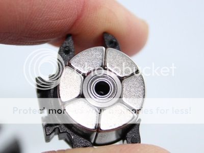
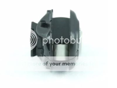
First take a look at this pretty little motor here :
It has some very interesting features which I believe make it an ideal candidate for a generator.
The plan is to attach it next to the braking disk with some additional magnets over the top larger holes, (those 8 holes in the picture), in order to make it turn using the eddy current principle. The magnets will fit in the holes with some steel ring on their back to close the magnetic circuit and isolate it from the coils inside.

Lets see some of it's features.


KV(RPM/V): 70
What does this mean? Obviously it produces 1V for 70 rpm. Lets do some math on that.
DD= Disk Diameter at the coupling point= 140mm
MD = Motor Diameter at the coupling point= 28mm (estimated from picture based on the given dimensions)
When these two are coupled give us a
GR = Gearing Ratio = 5 (140/28)

I calculated that for a speed of 25 Km/h the wheel turns at about 200 rpm, so for that speed the motor should turn at 1000 rpm. At that speed the motor/generator would provide 1000 (rpm) / 70 (rpm/V) = 14 V
With a proper circuit it should provide enough power to light up a Cree MK-R or any other power led easily.
I am using shimano ice tech rotors. They have a steel insert which interestingly would provide a loop to the magnetic circuit induced to the rotor, amplifying the effect! The generator can be positioned very close to the disk, creating a tiny air gap which would also strengthen the coupling.
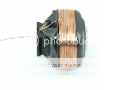
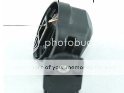
This motor is build using the DLRK winding, it has a negligible coging torque. It's very light, only 104 gr and with proper cirquitry it could make batteries obsolete, or it could just extend their capacity for ever!
So what you guys think of it?
 

Steve K

Flashlight Enthusiast
Joined
Jun 10, 2002
Messages
2,786
Location
Peoria, IL
well, since this is a brushless motor, I'm not sure that you can assume that you will get 1v for every 70 rpm in angular speed. Possibly you could get 70 rpm per volt applied, but there are obviously limits to that too.

The specs on this motor are pretty sparse... the max voltage, the max current, and max power are all listed as zero. It might make a person think that the specs weren't very thorough.

One key detail for using the motor as a dynamo would be the output power, and hopefully defined with the load that you plan to use.

100 grams might be a good weight, but you have to consider that this is just replacing the winding in the Magnic. I'm guessing that the motor is heavier, since the motor also has a bunch of magnets inside it.

Sounds like the next step is for you to buy one and see what sort of power you can get out of it at different speeds.
 

manokaiser

Newly Enlightened
Joined
Jul 12, 2011
Messages
3
Sounds like the next step is for you to buy one and see what sort of power you can get out of it at different speeds.
I am into it. Someone commented he tested with 2 and 3 cells, 2S 8V 450mA 3S 12,2V 670mA. That ofcourse is input, estimating an efficiency of 80% overall the motor would output ~6.5 W at that speed. Sounds good. We'll see what comes out of it when used as generator. I expect it to be close to that output anyhow.
 
Top