My Deus Ex: Human Revolution-inspired candelabra project

AnAppleSnail

Flashlight Enthusiast
Joined
Aug 21, 2009
Messages
4,200
Location
South Hill, VA
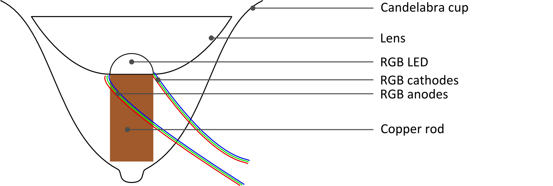
I'm stuck trying to solder the copper rod heatsink into place. I need a thermal connection between the LEDs and the candelabra and this is my solution:


The problem is that I'm unable to melt the solder/keep the candelabra heated/heat the copper rod. I've tried using a regular soldering iron to maintain an elevated temperature combined with my soldering gun (which is only meant to be switched on 12 seconds in every minute). I also try using a mini blow torch (about the size of a large permanent marker pen) but the flame keeps going out, presumably because it's upside down and getting blown out by hot oxygen-depleted air).

Arctic Silver thermal epoxy is also epoxy. Regular 10-ton epoxy in thin layers is reasonably thermally-conductive. My brazing torches run in most any position EXCEPT inside a bottle-shaped object. If you do not trust Arctic Silver, then you'll have to heat the base to puddle solder. Then use needlenose pliers you despise to hold the copper slug as you heat it quite hot. Press this onto the solder while heating the top of the copper slug. Once it sets, remove heat and hold it in place. Or use your second needlenose pliers and apply ice to quickly cool things. This will hiss and steam excitingly. You should probably not breathe the steam (Explains a lot about me, eh!?). Then attach LEDs and wires. I've made custom copper housings out of pipe and sheet copper this way.
 

seanspotatobusiness

Newly Enlightened
Joined
Jul 12, 2010
Messages
81
Hi. Thanks for all the responses! The use of solder is intended to thermally couple the LED to the candelabra via the copper rod. Due to the construction of the first candelabra I'm using, it will not be possible to drill and tap but I might try this for the second!

The LEDs will be attached to the copper rod using epoxy on the sides but with the interface filled with cheap white thermal paste.

Having looked up the thermal epoxies, I notice their conductivity is 0.7-1.0 W/(m.K), compared to 0.3 for regular epoxy (about 400 for copper). I'm not sure they're worth the additional expense.

I don't have a hot plate but I could maybe use the gas hob. I won't, unless the following plan fails, because I'm afraid of burning myself!

My current plan is to epoxy the rods in place and then to melt solder in the space around the rods using my blow torch with the candelabra at an angle to allow hot air to escape.
 
Last edited:

AnAppleSnail

Flashlight Enthusiast
Joined
Aug 21, 2009
Messages
4,200
Location
South Hill, VA
My current plan is to epoxy the rods in place and then to melt solder in the space around the rods using my blow torch with the candelabra at an angle to allow hot air to escape.

Try with just epoxy, please. Heating epoxy enough will burn it, leading to toxic fumes. I have found that desoldering with a torch is likely to create sufficient temperatures for common epoxy to burn. A thin layer of epoxy with wide surface contact is not much less thermally-conductive than a metal-to-solder connection (Near-zero 'meters' value in W/m*K gives low resistance).
 

seanspotatobusiness

Newly Enlightened
Joined
Jul 12, 2010
Messages
81
Okay, but the problem with using only epoxy is better illustrated in this modified diagram. The shape of the candelabra cup is such that there will actually be very little contact area between the rod and the cup. That's why I think I need something more conductive to fill the gaps. Perhaps I could epoxy the rod in and then just drip solder into place? The joints would be cold and I don't know whether they'd stay in place with the candelabra getting moved around during normal use.

D42px.png
 
Last edited:

bshanahan14rulz

Flashlight Enthusiast
Joined
Jan 29, 2009
Messages
2,819
Location
Tennessee
If it can't be damaged by heat, you could remove anything that would melt and just torch the copper and the cup until they are hot enough to wet teh solder and then just start feedign it lotsa solder.

Another idea is to have someone custom make you some aluminum sinks that will fit the space, or copper sinks if you can afford them.

Have you already tested the "optics" you will be using? I'd start there to make sure that a single RGB high power LED will give you the effect you are looking for with little/no color separation.
 

hellokitty[hk]

Enlightened
Joined
Jan 29, 2007
Messages
645
Why don't you just try putting the whole thing in your oven?
Just put a roll of solder in there and bake it.

Maybe you'll want to take a look at fx-sabers.com
They look pretty impressive to me :twothumbs Not meant for actual lighting though, but the lightsabers look pretty evenly lit.
 

RoGuE_StreaK

Enlightened
Joined
Apr 15, 2010
Messages
615
Location
Brisbane, Australia
Another cheap thing to experiment with for end-lit is cellophane (or whatever unbranded non-cellulose cheap stuff you can find in your local dollar store) - make a tube of it, rolling it say 10 times or more (ie. 10 layers), its bifringent properties combined with multiple layers helps spread the light. To a degree. Worth picking up a role for $2 to play with.
 

seanspotatobusiness

Newly Enlightened
Joined
Jul 12, 2010
Messages
81
I registered on the FX Sabre forum four days ago but they still haven't approved my registration. There is no contact information that I can find. I wanted to ask them about the cellophane since that's what's recommended in a thread in their forum.

Regarding the copper rods; on closer inspection of the cups, I noticed that there is some exposed thread (the cups actually screw onto this particular candelabra). I've ordered a tap and die set but the first one was out of stock and eventually my order was cancelled. I've ordered another from elsewhere and am awaiting dispatch.

Thanks again to everyone for their suggestions. I will update the thread as soon as I make notable progress (or hit the next obstacle)!
 

seanspotatobusiness

Newly Enlightened
Joined
Jul 12, 2010
Messages
81
It doesn't look like I'm getting onto the FX Sabres forum any time soon which is unfortunate because they've surely got an answer for this, but my current problem is the visibility of the outside edge of the diffusion film. I've ordered cellophane and will find out if it's any different from my current sheets.

The photo below shows the issue. Here, I've deliberately cut in various directions in order to break up the line and make it harder to follow but it's still quite clearly visible (the front tube is the one with film in - you can see a jagged line which is the outside edge of the film).

http://i.imgur.com/zwlwW.jpg


Your image is too large and has been replaced with a link. Please resize and repost.
See Rule #3 If you post an image in your post, please downsize the image to no larger than 800 x 800 pixels. - Thanks Norm
 
Last edited by a moderator:

seanspotatobusiness

Newly Enlightened
Joined
Jul 12, 2010
Messages
81
It's been a right kerfuffle, but all the LEDs are in position and connected. The current problem I'm addressing is that the supply I'm using provides 12.5 volts on all three channels. I reach typical current flow through each colour (I think 300 mA) at 9.7 v for blue, 7.4 v for red and 10.7 v for green. To drop, 2.8 v, 5.1 v and 1.8 v, I need 8 ohm, 14.6 ohm and 5.2 ohm resistances inline with the supplies.

I've bought an assortment of 1W resistors and can approximate the required resistance with:

6.8 ohm and 1.2 ohm in series for blue,
3x47 ohm and 1x270 ohm in parallel for red,
6.8 ohm and 20 ohm in parallel for green.

Together, they're dissipating just under 4W. I was hoping they could all be placed in the controller casing (there is definitely enough space) in this picture but I'm uncertain how much heat will build up inside it. Maybe I should locate the resistors outside of that controller?
KDLki.jpg
 

RoGuE_StreaK

Enlightened
Joined
Apr 15, 2010
Messages
615
Location
Brisbane, Australia
Those controllers use standard 0.1inch / 2.54mm pins/sockets (headers), you could make a little breakout board that plugs into the line and has a socket at the other end for your LEDs.
Or just unsolder the output cable from the controller board, solder in wires to your breakout board, then solder the original cable to your breakout.
May as well keep the resistors separate, maybe put them in a nice metal box that can double as a heatsink.

Also might need to use 2W resistors.
 

seanspotatobusiness

Newly Enlightened
Joined
Jul 12, 2010
Messages
81
Those controllers use standard 0.1inch / 2.54mm pins/sockets (headers), you could make a little breakout board that plugs into the line and has a socket at the other end for your LEDs.
Or just unsolder the output cable from the controller board, solder in wires to your breakout board, then solder the original cable to your breakout.
May as well keep the resistors separate, maybe put them in a nice metal box that can double as a heatsink.

Also might need to use 2W resistors.

Hi. Thanks, Rogue. Would these be suitable, for example? http://www.ebay.co.uk/itm/Latching-...al_Components_Supplies_ET&hash=item1c16bb3b40

If it's attached directly to my strip board, is there a risk of damaging the board when unplugging (do to the mechanical stress on the board).

I'm thinking metal project boxes are expensive for what they are... I might just epoxy the resistors to the underside of the candelabra base. That could work? I could then glue that controller circuit to the underside of the candelabra base and drill a small hole for the IR detector.

My final problem is insufficient collimation of the LED light. I'm using some cheap lenses from China that were meant to give collimation to five degrees but I'm still losing most of the light near the bottom half of the tube so that's definiately not what I'm getting. I realise that using cheap generic RGB LEDs means that I won't be able to find a lens perfectly designed to collimate their output.
 
Last edited:

seanspotatobusiness

Newly Enlightened
Joined
Jul 12, 2010
Messages
81
This project stalled because I couldn't get the ends of the tubes to look right. The tubes are frosted acrylic. For the ends of the tubes, I glued silver mylar film to a clear acrylic cylinder, inserted that cylinder into the end of the tube, sawed the cylinder off and then sanded it down. The result doesn't look very good.


I used rolled-up cellophane to try to distribute the light better but you can see where the edge contacts the tube.


The acrylic tubes I already have are 30 cm (1 foot) long with a 38 mm (1.5 inchs) outside diameter. Has anyone got any ideas on how to terminate the tubes in a way that doesn't look so bad? I might just not terminate them at all.

Here's a picture of the whole thing looking bad. I don't know how to maximise the dynamic range of my camera so the picture doesn't appear how I see the scene. Only the middle tube has the cellophane. I haven't yet put it in the others because I'm not yet happy with the tubes themselves (the ends of the tubes, specifically).


Mk II will probably use a chain of low-power RGB LEDs instead of single high-power ones.
 

seanspotatobusiness

Newly Enlightened
Joined
Jul 12, 2010
Messages
81
I've done what I think I should have done in the first place (but had no idea that it was a possibility until recently) which is contact a couple of people in the UK who make and sell LED-lit Star Wars light sabers. From them I'll buy the plastics including the tips.

Could anyone advise me regarding my next attempt in which I intend to link many low-power RGB LEDs in a chain.

If I attach all the legs together and each LED consumes 20 mA, a chain of 40 LEDs would consume 800 mA for each colour at 2.2 V (red) and 3.4 V (blue and green) which equates to 7.2 W. That's quite a lot of heat for something that has no mechanism to dissipate it, right? That would only be for one "candle" as well so I'd need to supply three times that. Perhaps I just can't have them at full brightness? Is the use of 5 mm versus 3 mm LEDs a consideration because the specifications I see on eBay make them look the same except 5 mm consumes more space?
 

Ken_McE

Flashlight Enthusiast
Joined
Jun 16, 2003
Messages
1,688
The LEDs on a stick will give good color control. Three fluorescent tubes standing on end would give a lot more light.
 

seanspotatobusiness

Newly Enlightened
Joined
Jul 12, 2010
Messages
81
I'm not sure what you mean by LEDs on a stick but if you mean what I think, the problem is that the light would have clear points of origin and not be diffused. I think a fluorescent tube would not look right because it needs an electrical connection at both ends.

I'm also thinking that I can't daisy chain 3/5mm LEDs together because the colours won't mix; I'll have distinctive red, blue and green sides for each tube (which incidentally is already somewhat problematic for my single-LED approach).
 

Ken_McE

Flashlight Enthusiast
Joined
Jun 16, 2003
Messages
1,688
I think a fluorescent tube would not look right because it needs an electrical connection at both ends.

Google for "fluorescent tube guards". They are clear plastic tubes sized so that a T-12 or T-8 bulb fits in them nicely. Set one on end with a base to steady it and hold it firmly in place. Run a single wire up the side in between the bulb and the holder, have it alligator clip to the upper end of the tube, come up with a decorative cover if you don't want people to see the end. Speaker wire is available with clear insulation, this would reduce its shadow. High brightness, quite close to what you want, low fuss.

Or if you really, really, must have that exact look, set clear tubes on end, saw open a bunch of cyalume sticks, pour the contents into the tubes, enjoy.
 
Last edited:
Top