minisystem
Newly Enlightened
- Joined
- Jul 12, 2011
- Messages
- 96
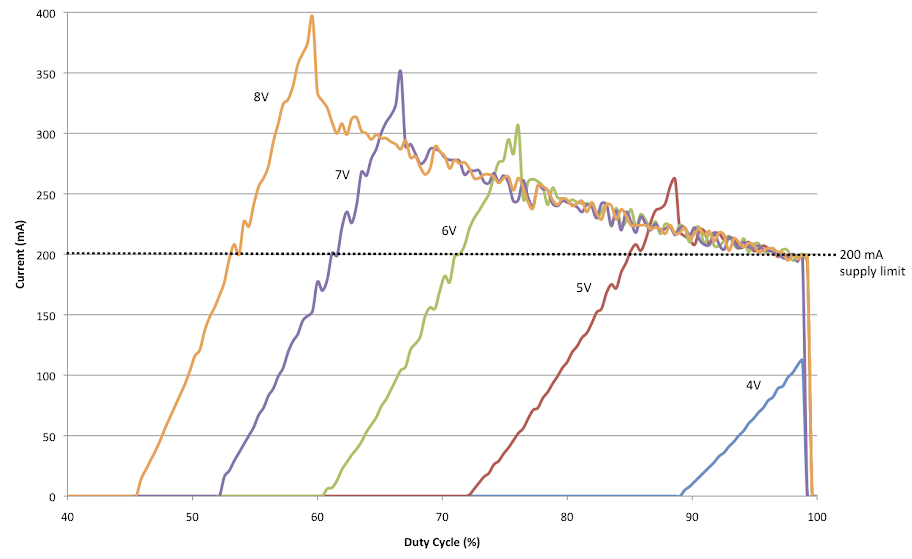
Performance is much much improved with the use of a mosfet driver in a synchronous topology. Right now, I just scan through the 255 PWM values to find a maximum and, for the most part, am able to extract peak or close to peak power from a current-limited bench top supply. Here is the schematic:
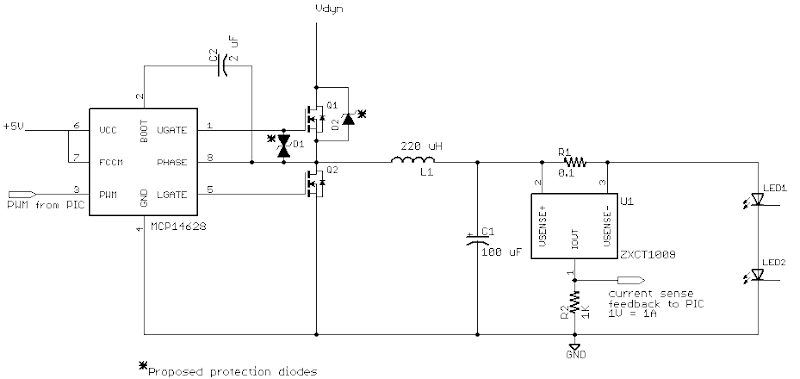
The mosfet driver takes PWM input from the Arduino and puts out a driver signal of the same PWM for the high side mosfet and an inverted signal for the low side MOSFET. The capacitor C2 is used to bootstrap the gate voltage for the high side MOSFET.
In this schematic, I'm using this MOSFET driver: MCP14628, but after briefly getting everything working I fried it. I also tried this one: LM2726. They seem to operate in very similar manners. In both cases, I can get the buck regulator working and find the peak power PWM setting, but keep frying the high side mosfet. I'm not exactly sure what circumstances are causing this. Maybe a surge on power up? In the case of the MCP14628, I also zap the high side driver output. The LM2726 seems to have survived whatever circumstances fried the high side mosfet. I'm assuming because I'm working with an inductor, there might be some transients that are exceeding the Vds or Vgs of the fets (30 and 20V respectively). I'm not working with anything beyond 7.5V limited @ 200 mA from the power supply.
I've proposed a couple of protection diodes that would have a breakdown voltage of just less than Vgs of the fets (20V). Hopefully that will fix the problem. Any thoughts?
")