Piezo Switch Questions

Klem

Enlightened
Joined
Mar 26, 2010
Messages
581
Location
Perth Australia
Storm Monkey...Can't answer all your questions but I do know you won't get more than 500ms (half a second) of continuity out of a piezo switch, regardless of how hard you press. Typically it's much less than that.

The way it works is the harder you press the longer the contacts close, but no more than half a second is possible in a typical piezo.

If your driver demands more than half a second to operate the modes then I can't see it working with a piezo. As Lucca said, it will have to be something else like a reed switch, or normal press-switch like a cheap $10 boat starter button.

Bear in mind if you use a normal momentary press-switch water pressure will push against your momentary and it could turn it into constant ON when you dive.

One of my first builds a few years ago used a boat starter switch. Luckily the thick rubber hood was so strong, and the shape naturally resisted being compressed. I say luckily because I hadn't even thought of that. Cut a long story short... it worked, but I never went below 20mts so don't know if the switch would have held out at greater pressures.

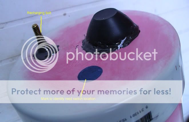
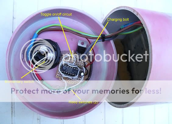
The completely sealed canister idea came unstuck when one of the reed switches fused closed. I used brass bolts for charging and the reed switches disconnected the positive bolt from the battery when not being charged. Put a magnet near the reed switches and the positive bolt went 'live'. Then I connected the bolts to a charger with a couple of croc clips. When fully charged, remove the magnet, so when diving the positive bolt was isolated and wouldn't short-out with the negative in salt water. I put the two charging bolts at opposite ends of the canister (furtherest apart I could get) just in case the bolts went 'live' when they weren't supposed to...which they did!

I can only think one of the reeds fused in the on position because of either being bashed about, or because the charger was pumping at 500mA, and the 2 reeds were 300mA each, in parallel. Who knows?!

When I drilled into it to fix the reed switches I found humidity and micro leakage had built up and was corroding all the wiring. There were droplets of water inside and it became all too hard to fix... that was the end of that torch.

Moral of the story...don't make your canister permanently sealed!

Couple of photos
firstbuild2.jpg

FirstBuild1.jpg
 
Last edited:

Klem

Enlightened
Joined
Mar 26, 2010
Messages
581
Location
Perth Australia
Wyager,

Mate, that'd be great!

One question...I take it this will make buying a drop-in driver redundant?

I understand a programmable chip will not only act as an interface between a piezo or reed switch but also manages the power to the lights, and can monitor battery life (by measuring voltage and give a wanring flash via the main light when nearly empty)?
 

DIWdiver

Flashlight Enthusiast
Joined
Jan 27, 2010
Messages
2,725
Location
Connecticut, USA
A piezo element generates voltage when you bend it. The voltage generated is proportional to the RATE at which you bend it.

In a piezo switch the element is attached to the flat surface that you press on. The bending of that surface (yes, the tiny deflection caused by your finger pressure!) generates enough voltage to turn on a MOSFET. You have to press it FAST enough to get it to operate. The gradually increasing pressure from the water will not do it. Also, there's no 'floor' to it, but it will continue to bend as you and the water exert more and more force on it. No matter how much force is already on it, if you press a little harder it will operate, at least until you break it!

D
 

wyager

Flashlight Enthusiast
Joined
Feb 10, 2010
Messages
1,114
Wyager,

Mate, that'd be great!

One question...I take it this will make buying a drop-in driver redundant?

I understand a programmable chip will not only act as an interface between a piezo or reed switch but also manages the power to the lights, and can monitor battery life (by measuring voltage and give a wanring flash via the main light when nearly empty)?

I'll try and draw something up tomorrow (I don't really like making schematics, probably because I've never really learned EAGLE or anything), but basically it would be like a simple driver, yes. Whether or not you want a drop-in regulator depends on whether or not you want a current regulated driver or anything. If direct driving the LED is OK, then you're OK without a secondary driver.

Monitoring the battery would be more difficult, to my understanding AVRs have some built in regulated voltage references for things like supply voltage measurement, but I've never messed with that stuff. I'm thinking simple on/off with some PWM.

Basically, I'm thinking this:
313-8-DIP.jpg

($2, can run down to 1.8v)

as well as a FET. You might want an extra transistor or resistor or two.

The code will be something like

Code:
int onoroff; //this lets the light remember if it's supposed to be on or off
DDRB |= (1<<3); //this will make pin 3 an output, will hook up to FET
DDRB &= ~(1<<2); //this will make pin 2 an input
PORTB &= ~(1<<3); //make sure light is off
while(1){
do{
}while(!(PINB & (1<<2)));//go in a loop until the piezo press is detected
onoroff = !onoroff;//change on/off state of light
if(onoroff){
PORTB |= (1<<3);//turn on
}
else{
PORTB &= ~(1<<3); //turn off
}
_delay_ms(100);//wait a little bit
}

That is a very simple piece of example code (probably full of errors) but it might help to give you a gist of what the idea is. "//" signifies a comment. Adding multiple levels, press strength measurement, etc would require more work.
 
Last edited:

Klem

Enlightened
Joined
Mar 26, 2010
Messages
581
Location
Perth Australia
Gav,

I suppose I could make a few of these toggle circuits up, for those that are not yet confident building their own.

If I charged commercial rates (for my time and profit) then the cost would climb. What I would like to see however is you guys giving it a go, get a soldering iron, source the parts, and have a crack.

If you want me to help with sourcing the parts then happy to do that, or take you through it one step at a time, fine also.
 

DIWdiver

Flashlight Enthusiast
Joined
Jan 27, 2010
Messages
2,725
Location
Connecticut, USA
It's large, it's power hungry, and it seems like a "dirty" method of getting this done. There are no pre-programmed micros for this task to my knowledge, but the benefits outweigh the marginal cost increases IMO. You have a much smaller chip with no external components needed, and it is able to perform much more complex tasks like sensing the amount of force applied to the piezo element (maybe a soft tap could be low mode) and it is able to intelligently change brightness levels by applying PWM to the FET.

This simplified circuit will work only if the battery voltage is within the 1.8-5.5V range throughout discharge. Otherwise, you will also need a voltage regulator to run the micro. And if you want to measure battery voltage, you will need a reference voltage, either from a regulator or a dedicated reference. But measuring voltage and keeping power super low adds a few more parts. And if you want to do high-duty-cycle PWM (to get low light levels) you might need a FET driver...

Still, all the stuff to do a really nice controller would easily fit on a board smaller than Klem's and less than 3/16" (4.5mm) thick.

If I were to lay out a board, write the firmware, buy boards and parts, then build and test a dozen, I'd estimate 50-75 hours, and about $300 materials. Then add another 20 hours to list it, answer questions, etc, and 5 hours to write a data sheet. At a paltry $5.00 per hour, the total comes out to a minimum of $56.25 per board. Even there it's likely many hours would be 'non-billable'.

If I were wildly optimistic and planned to sell 50 boards, I would go for $25 each (calculations not shown). Even at that price it's clearly a labor of love, which is why you don't see this board available comercially. If DX were to try to sell these at $4.35 each, one could only guess how many they'd have to sell before turning a profit.


D
 

wyager

Flashlight Enthusiast
Joined
Feb 10, 2010
Messages
1,114
This simplified circuit will work only if the battery voltage is within the 1.8-5.5V range throughout discharge. Otherwise, you will also need a voltage regulator to run the micro. And if you want to measure battery voltage, you will need a reference voltage, either from a regulator or a dedicated reference. But measuring voltage and keeping power super low adds a few more parts. And if you want to do high-duty-cycle PWM (to get low light levels) you might need a FET driver...

Still, all the stuff to do a really nice controller would easily fit on a board smaller than Klem's and less than 3/16" (4.5mm) thick.


D

The voltage thing is true-but 5.5v to 1.8v includes 2xAA, 1xCR123 and 1xLi-ion. Also, AVRs have internal voltage references, no external circuitry required. And keeping power draw low is probably easier to achieve with fewer parts IMO. Also, how much current do FETs take to activate? I think that a standard AVR pin can sink 20mA constant at Vcc.

Anyway, it's really up to the builder. If you don't think you can handle learning how to program a microcontroller, a 556 might be easier.
 

wyager

Flashlight Enthusiast
Joined
Feb 10, 2010
Messages
1,114
@wyager
start using C instead of bascom :sssh:

I think that's sarcasm...
At least C is better than ASM! It's just hardcore enough to be low-level while not being a total pain to program in. Also, there are no bascom compilers for OSX! :nana: I'm stuck with C or assembly, or processing+wiring I guess.
 

gav6280

Enlightened
Joined
May 1, 2008
Messages
556
Location
10 Min from NDAC.
Gav,

I suppose I could make a few of these toggle circuits up, for those that are not yet confident building their own.

If I charged commercial rates (for my time and profit) then the cost would climb. What I would like to see however is you guys giving it a go, get a soldering iron, source the parts, and have a crack.

If you want me to help with sourcing the parts then happy to do that, or take you through it one step at a time, fine also.


Hmm,well maybe a Kit then??

That way we could solder it all up ourselves and there is minimal time and effort for you, but we get all the right bits and and some drawings to help???:whistle:
 

lucca brassi

Enlightened
Joined
Feb 1, 2008
Messages
889
Location
US
I think that's sarcasm...

Eh no just joke ( at local electronics site have fun to argue about what is the best starting from asm up ( it is but is hard I hate M68000 HC ) or start from bascom or something similar

but atinny covering black :)

DSCN1395-ATTiny45-300.jpg


I work most with LabView and almost forgot others
 
Last edited:

DIWdiver

Flashlight Enthusiast
Joined
Jan 27, 2010
Messages
2,725
Location
Connecticut, USA
The voltage thing is true-but 5.5v to 1.8v includes 2xAA, 1xCR123 and 1xLi-ion. Also, AVRs have internal voltage references, no external circuitry required. And keeping power draw low is probably easier to achieve with fewer parts IMO. Also, how much current do FETs take to activate? I think that a standard AVR pin can sink 20mA constant at Vcc.

Anyway, it's really up to the builder. If you don't think you can handle learning how to program a microcontroller, a 556 might be easier.

The gate of a FET acts pretty much like a capacitor. So it takes virtually no current to keep it at any particular voltage, but it takes current to change it to a different voltage. If you don't care how fast you get there, you can use almost anything to drive it. I've seen a switch for pull up and 100K resistor for pull-down.

It's when you are doing PWM that you start to care about how fast the FET switches. For LED dimming, you want at least 100 Hz so you can't see the flicker. I like to go 200 Hz. And suppose you want 100:1 dimming. That's not as extreme as you might think. My dive light has 16:1 and the low setting is way to bright for some things. Your PWM cycle time is 1/200 sec, or 5 mS. At 1/100 duty cycle, the on-time is 50 uS. To keep the pulse kind of rectangular, you want the FET to turn on and off in something like 10 uS.

A large FET could easily have a gate charge of 50 nC, which would require 5 mA to turn on and off in 10 uS. AVR and PIC micros can easily handle this, but not all micros can. And if for some reason you want to go with higher PWM frequency or lower duty cycles (say for a Moon-Light mode), you could start to run into problems even with AVR or PIC.

For most hand-held lights, you probably won't need a FET driver. But when designing PWM circuits, particularly as you get into the higher power LEDs available today, it shouldn't necessarily be ignored.

D
 

wyager

Flashlight Enthusiast
Joined
Feb 10, 2010
Messages
1,114
So if the µC can't sink enough current, the waveform will be smoother? That's not necessarily a bad thing. In fact, that might be desirable.
 

georges80

Flashlight Enthusiast
Joined
Oct 23, 2002
Messages
1,262
Location
Sunnyvale, CA
There's some very nice FETs out there these days with high current, very low RDSon and total gate charge values <10nC and with gate thresholds below 2.5V. These could more than easily be driven by a AVR even at khz speeds with good switching performance. Just make sure the AVR you choose has symmetrical high and low drive currents - most of the newer ones do.

The gate threshold is likely a more important spec that any of the others if you are just trying to make a piezo toggle circuit that can run from single li-ion or lower voltage.

cheers,
george.
 

DIWdiver

Flashlight Enthusiast
Joined
Jan 27, 2010
Messages
2,725
Location
Connecticut, USA
So if the µC can't sink enough current, the waveform will be smoother? That's not necessarily a bad thing. In fact, that might be desirable.

Well, maybe. What happens is the efficiency drops (though at very low power, maybe you don't care) and the color shifts. Maybe you wouldn't care about that either, if it's just a light. It's important primarily for photography and video.

So I'll grant you that the FET driver is not needed.

D
 

gav6280

Enlightened
Joined
May 1, 2008
Messages
556
Location
10 Min from NDAC.
george - Would any of your drivers be suitable for use with a piezo switch without any modification or additional circuits?

As im think here aloud.....If some were then us diving chaps might buy them???
 

georges80

Flashlight Enthusiast
Joined
Oct 23, 2002
Messages
1,262
Location
Sunnyvale, CA
george - Would any of your drivers be suitable for use with a piezo switch without any modification or additional circuits?

As im think here aloud.....If some were then us diving chaps might buy them???

The main issue with a piezo is that it essentially acts like a momentary action which is great, but it can't readily provide longer on time if pressed for a long time... i.e. it really only can provide the momentary pulse which is somewhat dependent on the circuitry that converts the piezo voltage to a logic level and somewhat dependent on how hard you press.

Given that my UI's expect a 'press' to be able to do things a piezo wouldn't be able to replicate that aspect of a mechanical momentary action switch. Only a hall effect/magnet type switch could do that.

There's nothing in the various flex driver hardware that prevents a piezo style momentary switch from being used, it's the UI and firmware that prevents it.

It would essentially require 'dreaming' up a new user interface that responds only to 'clicks' versus clicks and presses....

cheers,
george.
 

georges80

Flashlight Enthusiast
Joined
Oct 23, 2002
Messages
1,262
Location
Sunnyvale, CA
Is a UI difficult to do?

hmmm.....

Maxflex 5 "piezo edition" (100%-50%-OFF)+Battery low warning.:whistle:

Yes, there's a lot of work that has gone into the existing firmware and LOT more testing. Each feature/mode that gets added requires testing and leads to more combinations/interactions that can go wrong.

The key to keeping things under control is to provide a single firmware release for all flex drivers (bflex,maxflex,hipflex,h6flex,d2flex) so that they all share the same source code base and all the manuals are consistent.

To provide a 'piezo' version would mean adding that feature to the source code and integrating it into the existing menu system. Without a 'press' it would mean that a string of clicks would be needed to set various menu modes etc - that would be a huge change to the entire menu system etc. Or it would need an internal true momentary action switch inside the housing in parallel with the piezo switch system so that for setting menu items etc that need the 'press' the internal switch could be used to do all the configuration and then the piezo would be used only for light level changes and on/off.

cheers,
george.
 

wquiles

Flashaholic
Joined
Jan 10, 2005
Messages
8,459
Location
Texas, USA, Earth
Yes, there's a lot of work that has gone into the existing firmware and LOT more testing. Each feature/mode that gets added requires testing and leads to more combinations/interactions that can go wrong.
+1

These so called "simple" changes are the ones that tend to create havoc on well running code :ohgeez:
 
Top