Copper does not need to be protected against oxidation where it's soldered onto of course. The rest can be protected by mask or silkscreening or tinning. Actually mask IS much better than gold plating for protecting against the environment, but that's mainly gonna come into play if it's exposed to moisture which really shouldn't happen anyways.
KeithInAsia said:
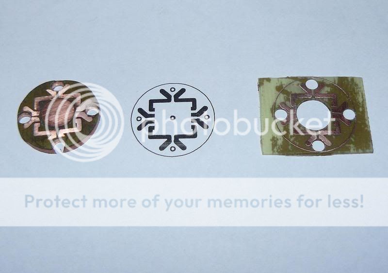
Look at that bottom of a Luxeon Rebel. Just how big is the surface areas of that thermal pad? It's very small. It looks to be about 2mm x 1.5mm. Just how much heat is going to travel through that point? All I have to do is match and slightly exceed that thermal area. That's it. I don't need a dozen vias to effectively match that thermal path on the LED.
Who told you this? Seriously, who?? The board is an insulator. The Rebel makes a fair amount of heat yet cannot be allowed to reach high temps. We really really need low thermal resistance.
The mfg never intended those Rebels to be mounted on a single-sided board without vias for example, not at full power. That wasn't their idea. Of couse even a single-sided board with a wide copper land is vastly improved than running the Rebel bare (which would burn it up in a second or two)- but no one would ever run a Rebel bare that's not relevant. Doesn't mean it's adequate. I mean doubling the area of the pad isn't twice the minimum cooling it needs. It's still many times less than the absolute minimum to run at even 350mA.
Spreading the heat only dissipates it through the board or off the top surface itself- the top surface's thermal resistance to air is way too high and it's totally ineffective if it's got a cover over it.
If the screws are stainless then the problem is that the stainless is a terrible thermal conductor. Like bad. 20x-30x less than copper. And unless there's thermal grease between the screw and board there's a significant boundary layer. I guess you could put grease in there but... well, stainless is just not an effective thermal conductor on this scale.
So if you discarded the vias you're limited to board conduction- which is 36C/W per sq cm on 0.9mm FR4. The round doesn't have anything like that. It's got under 1/2 a sq cm per device. So over 72C/W conduction through the circle board if it didn't have vias and we assumed the copper was so thick that the spreading is "perfect". That's terrible.
Again, we need 10C/W to be "good". That is, if you want to run it at full power, maybe a bit more, with a good heatsink behind it.
As we talked about- it is nearly impossible to actually measure the pad temp with any accuracy. I tried the delta-Vf method once but was somewhat disappointed, it's very small and hard to read. With photometric equipment, yeah, you could see the degradation in output as die temp increases, that'll be fairly clear on AlInGaP types. Perhaps you could engage someone here with that equipment?
It's not the board cost, but packing 6x Rebels on there is a fairly significant cost. And this is kinda silly because you're talking "common sense" based on feel- which doesn't mean much- and bogus ideas of measurement like heatsink temps and IR thermometers. Of COURSE gold plating reflects IR, plus the area is far too large. The measurement method is nonsense.
Vias are everything. Add vias. Many, many vias. For the most part the thicker you can place them the lower the thermal resistance, but eventually it may mechanically undermine the board's strength or the mfg's Design Rules Check will kick out your submission for not following the rules.
So what are you claiming these are? If a copper board is 5C/W or 10C/W, then are you saying it's less? What power level are you claiming they can sustain by design? 1A? 750mA? 350mA? Because I feel the way this is going to go is simply going to be you revising it to "well, obviously they work fine at >100C die temp because they're in use that way".