It works!!
Sorry, just had to say that loud

. I'm so glad it's working again...!
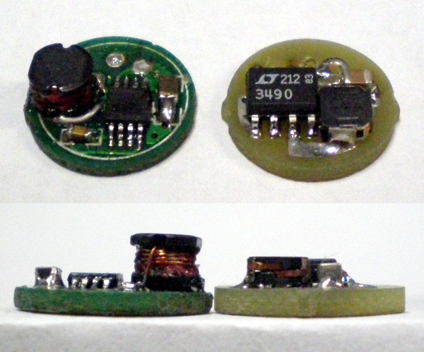
The final layout was done with the 3 x 3.2mm small Toko 1226 type coil in mind, since this is about the same size of the originally used coil. Heading for a lower resistance, I included the slightly bigger (3.7 x 3.9mm) Toko 1231 type in the efficiency calculation, being aware that it might already be too big. When I placed the order, I was eager to fit the bigger one in though, and finally managed to do it

.
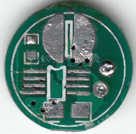
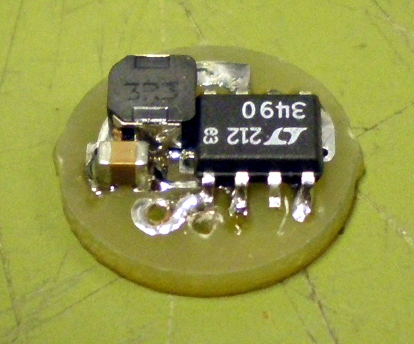
Please excuse the crappy pictures. Obviously a white background and the automatic macro mode of my cheap workshop-cam aren't a good match...
I wanted to have the copper coated in chemical gold but I only got HAL. Hope this is going to last at least another three years
.
Oh, and I have another three boards and three inductors left, so if you want to repair your LD-01, simply drop me a line :naughty:!
Thank you all again for your encourage and helpful tips!
 You're not making it easier for me...
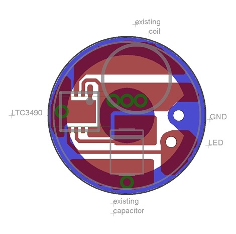
 ... Here's the new draft:
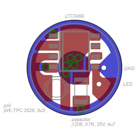

 !
!
 !
!