Steve K
Flashlight Enthusiast
Re: Will this circuit work?
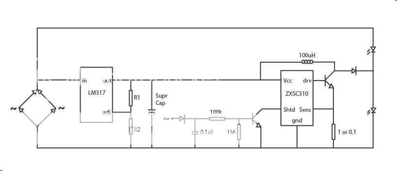
In my circuit, R4 and C2 form a low pass filter. This filter smooths the AC voltage into something much closer to a constant voltage. This keeps the standlight turned off when the AC voltage drops to zero (which happens twice during the AC waveform, or about 52 times for each revolution of my SON dynamo). D1 allows current to flow into C2 and be stored there. If D1 is removed, then C2 will discharge through the LED, and the standlight would turn on.
looking at your circuit... am I correct in thinking that this is not going to be a combined headlight and standlight?
It looks like your intent is to make just a stand-alone standlight.
If you plan to wire this in parallel with a regular headlight, you should know that this is probably not going to work. If it is wired in parallel with a regular headlight, this standlight will turn on at a lower voltage than the headlight, and will try to absorb all of the current from the dynamo.
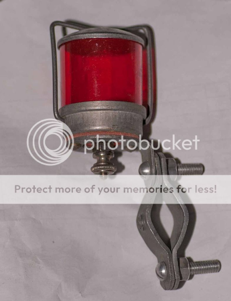
When I made a front standlight that was separate from the headlight, I used the front standlight shown in the schematic and photo in my previous post. This was wired in series with the headlight, and used the voltage drop across a bunch of paralleled yellow LEDs to charge a nicad battery. The yellow LEDs only conducted current in one direction, so I used red LEDs (as a taillight) to conduct current in the opposite direction. A rectifier diode could replace the red LEDs if a taillight isn't needed.
......
This is the circuit i built: Link in Flikr
I was referring to the one equivalent to the D1 in your first circuit, i just tried to connect R4/C2 to the + side of the rectifying diodes, i guess maybe some flow from the supercap can go to the shutdown without it.
In my circuit, R4 and C2 form a low pass filter. This filter smooths the AC voltage into something much closer to a constant voltage. This keeps the standlight turned off when the AC voltage drops to zero (which happens twice during the AC waveform, or about 52 times for each revolution of my SON dynamo). D1 allows current to flow into C2 and be stored there. If D1 is removed, then C2 will discharge through the LED, and the standlight would turn on.
yes i will only use one led Cree Led... i will make some test including more or maybe a couple of 5mm
looking at your circuit... am I correct in thinking that this is not going to be a combined headlight and standlight?
It looks like your intent is to make just a stand-alone standlight.
If you plan to wire this in parallel with a regular headlight, you should know that this is probably not going to work. If it is wired in parallel with a regular headlight, this standlight will turn on at a lower voltage than the headlight, and will try to absorb all of the current from the dynamo.
When I made a front standlight that was separate from the headlight, I used the front standlight shown in the schematic and photo in my previous post. This was wired in series with the headlight, and used the voltage drop across a bunch of paralleled yellow LEDs to charge a nicad battery. The yellow LEDs only conducted current in one direction, so I used red LEDs (as a taillight) to conduct current in the opposite direction. A rectifier diode could replace the red LEDs if a taillight isn't needed.
")