You are using an out of date browser. It may not display this or other websites correctly.
You should upgrade or use an alternative browser.
You should upgrade or use an alternative browser.
what's the difference between XML vs XML2 ?
- Thread starter picard
- Start date

So, does it generate the same amount of heat at the same lumen value?
More efficient means that more energy is converted to light, thus lowering the amount of heat generated.
RoGuE_StreaK
Enlightened
Really depends on your heatsinking and how long you are going to be running them at a time. If you can get the heat out before it builds up then yeah you could likely push it further than 3Amps. Recommendation would probably be for a direct-to-copper MCPCB to try to get as much heat out and spread as efficiently as possible, then figuring out your heatsink; if your path from the LED heatpad to the heatsink is restricted, then no matter how good a heatsink you have you are going to have bottlenecking issues at these higher currents.
RE: needing a passive heatsink (other thread), you might need to investigate heatpipes, but they are expensive. Cheapest source is probably from computers, see if anyone isn't using their powermac anymore
PS. From what I've read along the way you should take the IR gun readings with a grain of salt; can't remember the specifics though. Might be to do with not being able to get a reading of the actual junction?
")
RoGuE_StreaK
Enlightened
Direct-to-copper is the latest craze going around here; not only is it a copper board instead of aluminium, the major point is that the LED's thermal pad is actually soldered directly to the copper, rather than onto an intermediary copper plane that is bonded to the underlying board. This bonding was a bottleneck. The theory (and seemingly tests bear it out) is that there is a much more direct and unrestricted thermal path which goes directly to a copper heatspreader (the board), meaning you have a big area to transfer your heat out of into your heatsink, meaning you could be able to suck out the heat before it builds up in the junction and is detremental to performance/longevity.
NB: the ideas have been tossed around here for several years, but only really recently have some manufacturers started mass-producing them, making it a hell of a lot cheaper; you can get them for about $2 each somewhere around here, as opposed to the previous custom machining costs of say $30 a pop.
NB: the ideas have been tossed around here for several years, but only really recently have some manufacturers started mass-producing them, making it a hell of a lot cheaper; you can get them for about $2 each somewhere around here, as opposed to the previous custom machining costs of say $30 a pop.
DIWdiver
Flashlight Enthusiast
To be more specific, it isn't just the bonding, it's the thin layer of fiberglass insulation (it's actually a very thin circuit board) that causes the thermal 'bottleneck'. The conductivity of FR4 (commonly used PCB material) is about 1400 times less than copper, and about 700 times less than aluminum, so even a very thin layer has a big impact.Direct-to-copper is the latest craze going around here; not only is it a copper board instead of aluminium, the major point is that the LED's thermal pad is actually soldered directly to the copper, rather than onto an intermediary copper plane that is bonded to the underlying board. This bonding was a bottleneck. The theory (and seemingly tests bear it out) is that there is a much more direct and unrestricted thermal path which goes directly to a copper heatspreader (the board), meaning you have a big area to transfer your heat out of into your heatsink, meaning you could be able to suck out the heat before it builds up in the junction and is detremental to performance/longevity.
RoGuE_StreaK
Enlightened
Yes. 'tis.So with a direct to copper board the insulating layer will only be beneath the solder pads and not beneath the heat pad in the middle? Sounds awesome
Not in South Africa, but someone here (vestureofblood I believe?) is selling them for extremely reasonable prices, with only a couple of bucks shipping anywhere in the world. In fact, the pricing is much much better than actually ordering direct from the manufacturer!? :huh:doubt that I can get those reasonably priced in South Africa though!
-Die shrink of around 10%
That's the first I've heard of this. Got any links to prove that?
Can anyone make a generalization of how a smaller die would effect the light output from an optic. For example, if you have an 10 degree FWHM optic on an XM-L, how would you expect the light output through the same optic with and XM-L2 with a smaller die to change?
tstartrekdude
Newly Enlightened
- Joined
- May 17, 2008
- Messages
- 107
The entire beam profile will be 10% smaller and given the same light output from the die it will have 10% higher lux. Both of which are basically unnoticeable unless directly comparing the two side by side, and even then you would have a very hard time differentiating the two.
This would apply to any optical system you are using.
This would apply to any optical system you are using.
verysimple
Newly Enlightened
- Joined
- Sep 6, 2012
- Messages
- 41
But those won't come out until later next week..
And hopefully XML3 will be 20% brighter than XML2, than XML4 will be 20% brighter than XML3...
RoGuE_StreaK
Enlightened
Re: Cree xml vs cree xml2.
v2 has a silver board, v1 has green
v2 has a silver board, v1 has green
samgab
Flashlight Enthusiast
Re: Cree xml vs cree xml2.
Difference in performance, eg:
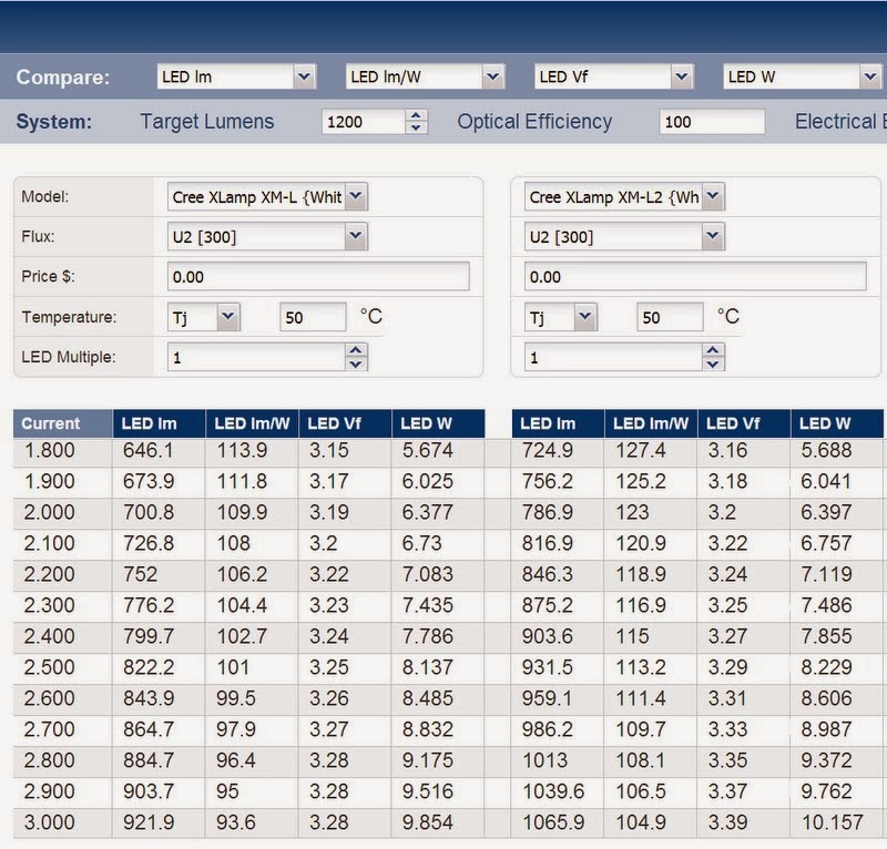
And in appearance, at a glance; an XM-L emitter has 3 bond wires and 4 visible segments, whereas an XM-L2 has 2 bond wires and no visible segments.
It has the same mechanical and optical footprint, however.
What's the difference, and what do I look for to tell the difference between the two?
Sent from my SCH-I545 using Tapatalk
Difference in performance, eg:
And in appearance, at a glance; an XM-L emitter has 3 bond wires and 4 visible segments, whereas an XM-L2 has 2 bond wires and no visible segments.
It has the same mechanical and optical footprint, however.
RoGuE_StreaK
Enlightened
Re: Cree xml vs cree xml2.
I haven't seen a comparison layed out like that before, it's... a bit of a *****?! If you work off a CC basis, then the Vf has actually increased, which is NOT where I want it to go; drive it at the same current as you used to and you now need more voltage on hand. Inversely if you look at the lumens, you could say roughly that you are getting the same lumens at the same Vf, but with a lower current. A little bit of a catch 22, kinda increasing efficiencies but not in a way that lets you drive it harder?
I haven't seen a comparison layed out like that before, it's... a bit of a *****?! If you work off a CC basis, then the Vf has actually increased, which is NOT where I want it to go; drive it at the same current as you used to and you now need more voltage on hand. Inversely if you look at the lumens, you could say roughly that you are getting the same lumens at the same Vf, but with a lower current. A little bit of a catch 22, kinda increasing efficiencies but not in a way that lets you drive it harder?
LEDAdd1ct
Flashlight Enthusiast
Re: Cree xml vs cree xml2.
The screenshot above is from the Cree tool.
Usage of the tool has answered many of my questions without posting and stopped
me from starting countless threads.
In my opinion, the two best tools are:
Cree Tool
Runtime Tool
I haven't seen a comparison layed out like that before...
The screenshot above is from the Cree tool.
Usage of the tool has answered many of my questions without posting and stopped
me from starting countless threads.
In my opinion, the two best tools are:
Cree Tool
Runtime Tool
samgab
Flashlight Enthusiast
Re: Cree xml vs cree xml2.
Oh yeah, thanks LEDAdd1ct, I should have posted a link to -and mentioned- my source, the Cree PCT. But thanks for posting those two links. They are very useful tools.
Oh yeah, thanks LEDAdd1ct, I should have posted a link to -and mentioned- my source, the Cree PCT. But thanks for posting those two links. They are very useful tools.
Similar threads
- Replies
- 14
- Views
- 3K
- Replies
- 1
- Views
- 687