XPG R5 Solitaire Mod. with 10280 & Two Stage Tail cap Switch

Benson

Flashlight Enthusiast
Joined
Feb 15, 2009
Messages
1,145
Re: XPG R5 Maglite Solitaire 10280 Li-ion

Hmmm... if 400mA is a good drive level, surely 350mA must be good, too. I'm now thinking of making a regulated 10440 solitaire with a single AMC7135 chip in the tailcap.

Thanks for the inspiration!
 
Last edited:

ma_sha1

Flashlight Enthusiast
Joined
Jan 10, 2009
Messages
3,042
Location
CT, USA
Re: XPG R5 Maglite Solitaire 10280 Li-ion

I'm now thinking of making a regulated 10440 solitaire with a single AMC7135 chip in the tailcap.
Thanks for the inspiration!

You are welcome, but the soli. tail cap has a hole of ~6mm ID,
how are you going to fit a AMC7135 :confused:
 

Al Combs

Enlightened
Joined
Jul 2, 2007
Messages
872
Re: XPG R5 Maglite Solitaire 10280 Li-ion

You could always drill/ream the hole in the tailcap larger if you needed. But how would you get positive to the Vdd pin of the chip? You could cut a slot down the length of the body to run a thin wire. If you got lucky, it wouldn't break through the side. But them how would you screw the tailcap on without twisting the wire off? You'd need some kind of disk/wiper system to transfer positive to the chip in the tailcap.

If you take the plastic switch body out of the front, you'd have plenty of room for the chip there. It would be a challenge. But ultimately I think easier than in the tailcap. You could glue the battery contact you're no longer using onto the end of the chip for positive pickup. Screw a wire into the side of the light for negative pickup. And then pot the whole assembly into the front of the light. The switch would of course be the "ma_sha1" twisty variety.

As far as screwing the negative lead to the side of the light, even if you used a 1.4 mm countersunk screw, you may not be able to do it in the front and still screw the reflector on. Soldering aluminum is normally thought to be impossible. There was a thread on it here once I remember. A Google of "soldering aluminum" brings up these two links in the first page, link-1 and link-2. Link-2 is a kind of brazing rod. The idea is the core of the rod scratches the surface while the flux prevents the oxygen from reaching the fresh surface. Once the aluminum is tinned with a microflame torch, an ordinary soldering gun can be used to attach the wire.
 

ma_sha1

Flashlight Enthusiast
Joined
Jan 10, 2009
Messages
3,042
Location
CT, USA
Re: XPG R5 Maglite Solitaire 10280 Li-ion

The switch would of course be the "ma_sha1" twisty variety.

Actually, The simple twisty switch wouldn't be a "ma_sha1" switch, as there's others who've done Soli. LED mods years ago, 3mm/5mm/luxeon etc. who have moded similar twisty switch way before me.

However, the picture below shows my latest Solitare invention:
Two Stage Solitare Twisty Tail Cap switch. I am pretty sure it's never been done on solitare before, so I am ok if you call it the "ma_sha1" twisty switch :devil:
img3491t.jpg


The center of the tail cap now has two contact points to battery, the outer spring loaded contact & center solid contact. Each is connected to a separate resistor. When screw it in, outer spring contact (Connected to 5 Ohm resistor) reach the battery first & turn on the low. Then, screw it further, the center solid contact (Connected to a 2 Ohm resistor) also reach the battery & turn on the High mode (This is due to 2 Ohm & 5 Ohm resistors in parallel gives ~1.4 Ohm combined resistance). Obviously, one can adjust the resistor values & achieve their ideal Hi/Low values. These are simply the two tiny resistors I have on hand.

Low mode: 5 Ohm resistor
img3487c.jpg


High Mode: 1.4 Ohm (2 & 5 Ohm in parallel)
img3488p.jpg
 
Last edited:

Benson

Flashlight Enthusiast
Joined
Feb 15, 2009
Messages
1,145
Re: XPG R5 Maglite Solitaire 10280 Li-ion

You are welcome, but the soli. tail cap has a hole of ~6mm ID,
how are you going to fit a AMC7135 :confused:

Well, the 7135s on my 1.4A boards (which is where I'd swipe one from) are SOT-89; they're entirely contained in a 4.5 x 4.1 x 1.5 mm bounding box, so it should actually be possible to pot a bare chip with wires soldered on in the 6mm hole. More likely, though, I'll enlarge the hole somewhat, cut out the section of PCB it's mounted on (taking care regarding what traces run clear to the cut edges), bulk up the connecting trace with solder, and press-fit it in the bare aluminum hole, hopefully establishing a decent mechanical, electrical and thermal connection. If I get the light to where I'm happy with it, I could then pot it for permanence and slightly better thermal connection.

But how would you get positive to the Vdd pin of the chip? You could cut a slot down the length of the body to run a thin wire. If you got lucky, it wouldn't break through the side. But them how would you screw the tailcap on without twisting the wire off? You'd need some kind of disk/wiper system to transfer positive to the chip in the tailcap.
Good point -- I had planned to run fine wire in a groove (and I prefer to think of it as skill, not luck :cool:), but hadn't considered the rotary joint issue.

*rethinks approach*

Hey, if I strip the heatshrink from the + end of a 10440 and load it "backwards", then I should have access to a + nub and a - ring at the tailcap. I admit I don't really like the idea of needing a non-standard (and relatively difficult to charge safely) battery, but it does seem workable.
:green: No, just thought about it, and that leaves the - end at the LED. So I'd have to run the wire the other way.

I'll think about this some more before I start modding...


And if you're wondering why I want to do it in the tailcap so bad, I had an idea similar to ma_sha1's new 2-stage twistie. I was trying to figure out how to make it regulated when twisted gently, but short to DD when tightened completely. That's looking a little intricate, so the other option I was thinking is to drill and ream a thru hole, make up a little push-button, and rig things such that loose = off, twist tight = on (regulated), and twist closed + push button = turbo (DD). Either of these requires access to the AMC7135's output, to short it to -, so if the AMC7135 isn't in the tailcap, you face the wire-next-to-battery issue all over again.

Now I may not be ambitious enough to implement either of those schemes, at least the first time. I can always pick up another solitaire and do it again with more features, if the first time works; just want to do this one the same way so the lessons learned apply.

Of course, since I'm not using 10280s, and may not even use an XP-G at first (none on hand -- I may cram an XR-E in instead), this is really OT in this thread. I'll start my own thread when I actually start construction.
 

Neondiod

Newly Enlightened
Joined
May 8, 2009
Messages
73
Location
Sweden
Re: XPG R5 Maglite Solitaire 10280 Li-ion

(This is due to 2 Ohm & 5 Ohm resistors in parallel gives ~3.5 Ohm combined resistance).
How did you come to 3,5 Ohm? I get 1,4 Ohm with 2 and 5 Ohm parallel.
Anyway, great mod!
Does anyone know if there is a neutral or ww rebel on 10mm round mcpcb? I would like a warmer tint than what's aviable with the current XPG's.
How many lumens does a standard solitare put out?
BR
 

ma_sha1

Flashlight Enthusiast
Joined
Jan 10, 2009
Messages
3,042
Location
CT, USA
Re: XPG R5 Maglite Solitaire 10280 Li-ion

Good point -- I had planned to run fine wire in a groove (and I prefer to think of it as skill, not luck :cool:), but hadn't considered the rotary joint issue.

I had a P7 with a tail switch & was thinking about putting in multi mode IC into the tail cap, the same problem, couldn't get over the rotary joint issue.

However, if you open up a protected Li-ion, you'll see that they run a thin wire from bottom to top, bottom is where the Protection IC chip sits. You could make a 7135 modified 10440 battery the same way for regulation, so the Li-ion is "Current regulated" & 7135 sit at the tail end but doesn't actually go into tail cap.

But it's a lot easier to put regulation up on top, where the switch is.
 
Last edited:

ma_sha1

Flashlight Enthusiast
Joined
Jan 10, 2009
Messages
3,042
Location
CT, USA
Re: XPG R5 Maglite Solitaire 10280 Li-ion

How did you come to 3,5 Ohm? I get 1,4 Ohm with 2 and 5 Ohm parallel.
Anyway, great mod!
Does anyone know if there is a neutral or ww rebel on 10mm round mcpcb? I would like a warmer tint than what's aviable with the current XPG's.
How many lumens does a standard solitare put out?
BR

You are right, I messed up the calculation.
2&5 in parallel = (2x5)/(2+5)=10/7=1.4 Ohm, not 3.5 Ohm. I corrected my original post above.

For the Soli. Original Lumens, there was a post a while back stated:
(using NiMH battery)

"-Maglite Solitaire incandescent: 1 lumen
- Maglite Minimag 2AAA incandescent: 5 lumens
- Maglite Solitaire MJLED: 5 lumens"
 
Last edited:

ma_sha1

Flashlight Enthusiast
Joined
Jan 10, 2009
Messages
3,042
Location
CT, USA
Here is something you don't see everyday:
A super tiny key ring 10280 spare battery holder made from half a Solitare.

  • Cut down & re-thread to 11x1.0 all the way through
  • Cut the thread section of the "neck" to make a washer
  • Thread the washer to the bottom to lock the bottom of the battery tube
  • Finish the bottom with carbon fiber trim plate
  • Tail cap trimmed ~3mm off to make this as short as possible
  • Tail cap open & close to load & unload battery
  • The whole thing is about 1/2 the size of Mag Solitare
  • 1mm play room after loading the battery to make sure there's no electrical shorting.

img3522mh.jpg


img3528.jpg
 
Last edited:

TheInvader

Newly Enlightened
Joined
Jul 16, 2009
Messages
109
You'll have to trim it. The Soli's outer diameter is actually 12mm.
10mm fits perfectly. As ma stated, a Cutter board was perfect.
 

rufusbduck

Newly Enlightened
Joined
Jan 13, 2009
Messages
81
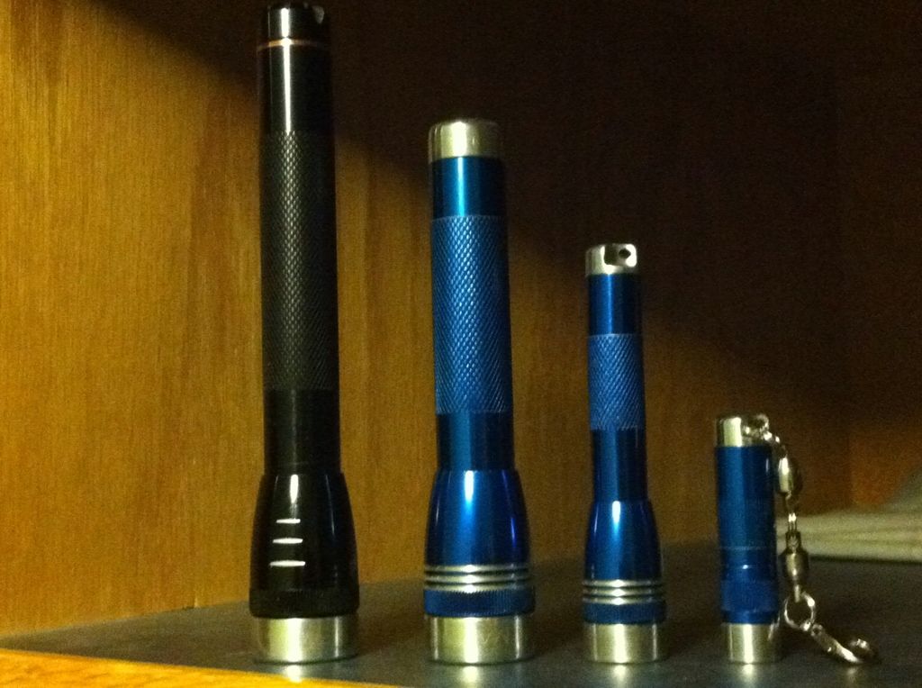
Here are some of my chops left OL AA, left center 14650 AA, right center AAA with cut driver, 10180 Nichia solitaire with single 7135 chip in pill replacing switch.
29A9CD03-8F19-434A-933C-354C23B6F3EF-234-00000115A8BEECED_zps57aa41c5.jpg
 
Last edited:
Top