Standlight circuits (Will this circuit work?)

Bandgap

Enlightened
Joined
Aug 14, 2002
Messages
284
Location
London
Re: Will this circuit work?

To maximize the amount of charge stored on the cap, I scribbled out this little circuit:


This I like
Simple and fast charging
- providing there is always some sort of load on the supercap to stop the volts going too high.

Steve
 

Alex Wetmore

Newly Enlightened
Joined
Nov 13, 2008
Messages
32
Re: Will this circuit work?

Ooops.
I have been off-line for a few days.

Circuit charging at 6V - which is indeed too much for the supercap

My calculations show 5.3V for 240 and 820 Ohms.
Did you use exactly those?
If so, the 820 need to be a little lower.

Vout = Vref(1+R2/R1)

For our circuit that is:
Vout = 1.25(1+820/240) = 5.52

That is a little high. I didn't measure my resisitors exactly and since they are +/-5% and Vref has a range of 1.2 to 1.3 volts you can easily end up over 6 volts. Here is a worst case example:
Vout = 1.3(1+861/228) = 6.2

By the way: If you want to have a high-current (greater than 50mA ) standby, supercaps are the wrong technology in my view.

What do you like instead?

The reason that I disagree with that statement is that they clearly work well in commercial headlights. The IQ Fly dims in standlight mode, but still puts out more light than the 30-50ma that works well for this circuit.

alex
 

Bandgap

Enlightened
Joined
Aug 14, 2002
Messages
284
Location
London
Re: Will this circuit work?

Here is a worst case example:
Vout = 1.3(1+861/228) = 6.2
alex

Fair point - did you actually measure 6V on your circuit.
If it was for mass-production, I would do it differently.


What do you like instead?
The reason that I disagree with that statement is that they clearly work well in commercial headlights. The IQ Fly dims in standlight mode, but still puts out more light than the 30-50ma that works well for this circuit.
alex

50mA is only 20 seconds from a 1F capacitor - maybe 40 with a 2V difference (CdV=IT).
To me, that is not long enough.
I realise this time is longer if the current decays exponentially.
I like about three minutes.

Interesting that the IQ fly is running on more than 30-50mA - or am I misunderstanding.

Some people are trying to get a lot more current to have a standby that is the same as travelling intensity.

I would think about rechargeable - or replaceable - batteries for a bright front standlight.

Each to their own

Steve
 

FrontRanger

Newly Enlightened
Joined
Oct 22, 2007
Messages
166
Location
Colorado, USA
Re: Will this circuit work?

What do you like instead?

Unless someone has a homebrew flywheel energy storage device ;) I think the only other practical thing for a bicycle light is a battery, so I'll venture that's what Bandgap means.

I have a B&M d'Lumotec Oval N-plus, and I appreciate the quality of its standlight. I do think useful things can be done with supercaps. I've been told that the commercial standlight circuits are really complex, and presumably the designer felt that the performance improvement was worth accepting the additional complexity. Personally, if I were making a home-built standlight I would use something much simpler with a modest performance degradation.

With that said, I now use a self-built LED dynamo light with no built-in standlight. A flashlight, which I require anyway for repairs in the dark, sits on my bars and performs the standlight function. As I've mentioned before, I think this is the simplest solution of all. As always, your mileage may vary.
 
Last edited:

Calina

Enlightened
Joined
Jul 26, 2006
Messages
955
Location
Longueuil, Québec
Re: Will this circuit work?

Did anybody tried to figure out the IQ fly circuit?

How about a combination super-cap + battery? Batteries don't do very well in cold weather.
 

syc

Newly Enlightened
Joined
Jun 10, 2008
Messages
155
Re: Will this circuit work?

I've seen a few battery based circuits floating around, but it seemed that the main problem with them is avoiding overcharging the batteries. Perhaps with the regulator circuit in this thread, you could have a battery powered LED that was recharged by the dynamo. That would actually be quite nice, imo.
 

Alex Wetmore

Newly Enlightened
Joined
Nov 13, 2008
Messages
32
Re: Will this circuit work?

Fair point - did you actually measure 6V on your circuit.
If it was for mass-production, I would do it differently.

Yes I did.

Interesting that the IQ fly is running on more than 30-50mA - or am I misunderstanding.

I think that they are. To get runtime I'm guessing that they use a more advanced circuit which boosts the voltage output from the cap. I wish B&M made their headlights easier to open up and explore.

Some people are trying to get a lot more current to have a standby that is the same as travelling intensity.

I don't desire that, but it should be bright enough to be noticable for a driver off to my side. Putting the standlight on a narrow beam optic reduces the usefulness of that.

I'm beginning to wonder if the best approach is to use 3 optics and LEDs. 2 would be used as driving lights and would be on when riding. The third would be used only as a standlight, run at reduced current, and have a wider beam angle.

At this point I'm mostly interested in the circuits. I don't consider standlights to be a requirement, using a small helmet light (like the Cateye EL-400/410) is a more suitable replacement than a real standlight.

alex
 

syc

Newly Enlightened
Joined
Jun 10, 2008
Messages
155
Re: Will this circuit work?

I finally got the breadboard from a friend tried out the most basic circuit, and found the results underwhelming. I'll try out frontranger's clamped circuit feeding off 7.2v and report back. I'll also try it with a second supercap in series instead of diode clamps and with the clamps but the 2nd supercap in parallel and see how it goes.

edit: After talking it over with a friend, it seems that keeping the clamp but using the supercaps in parallel is the most reasonable thing to try if I'm only powering one LED.


I'm beginning to wonder if the best approach is to use 3 optics and LEDs. 2 would be used as driving lights and would be on when riding. The third would be used only as a standlight, run at reduced current, and have a wider beam angle.

Assuming any of this stuff ever gets off the breadboard, I was thinking a triple LED setup with 2 narrow optics, and 1 oval optic. The oval optic would be backed by the supercap(s).
 
Last edited:

FrontRanger

Newly Enlightened
Joined
Oct 22, 2007
Messages
166
Location
Colorado, USA
Re: Will this circuit work?

I finally got the breadboard from a friend tried out the most basic circuit, and found the results underwhelming. I'll try out frontranger's clamped circuit feeding off 7.2v and report back. I'll also try it with a second supercap in series instead of diode clamps and with the clamps but the 2nd supercap in parallel and see how it goes.

edit: After talking it over with a friend, it seems that keeping the clamp but using the supercaps in parallel is the most reasonable thing to try if I'm only powering one LED.

Your friend is right. Two 5.5V caps in series can easily tolerate 7.2 V, but their effective capacitance is half of a single cap, and they can only discharge down to 2x nearly-off LED Vf. The second method will double the energy stored.

Also, as I mentioned earlier, the resistor value was approximate, because the diode drops were approximated. You can either play with the resistor value, or measure the diodes drops and calculate. If you have a solderless breadboard and a nice complement of resistors, I bet the former is faster.
 

syc

Newly Enlightened
Joined
Jun 10, 2008
Messages
155
Re: Will this circuit work?

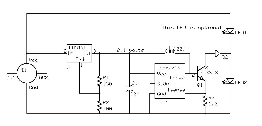
I updated the original diagram with the LM317L circuit on flickr and replaced with a diagram with a warning about tolerances and the worse case possibility. I've updated the link in my original message here, but other messages (such as Alex's) will have broken images.

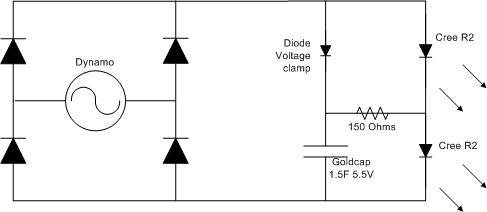
I also built up the circuit variation that frontranger suggested to improve the charge voltage of the supercap. After building it and taking some measurements, I was only seeing a little over 6v across both of the Cree R2's, and the diode clamp was dropping the charge voltage at the supercap to just over 4v.

It turned out that a single diode provided enough of a drop so that the supercap got just over 5v, and this is what I ended up with:

3036697865_82043cda16_o.jpg


The standlight seemed decent for a "be seen" light and it lingered around for quite some time. But I think I'm going to pick up a 50 and 100 ohm resistors and see it looks with those - the second supercap may come in handy with the lower resistance.

I'm really glad that there was so much feedback on these circuits as well as getting a chance to prototype it - this current circuit seems much better than the original one that I wired up last night.
 

cbr2702

Newly Enlightened
Joined
Oct 29, 2008
Messages
14
Re: Will this circuit work?

Unless someone has a homebrew flywheel energy storage device ;) I think the only other practical thing for a bicycle light is a battery

I realize I couldn't expect to do this as a DIY project, but would it be feasible for a hub dynamo maker to include a flywheel?

I would think a larger hub would help with this, as the larger the moment of inertia the more energy the flywheel can store. But if you make the spokes too short they don't work as well. So two things that come to mind for me are:

1) a full wheel dynamo. You know how cars can have those wheels where part of the wheel keeps spinning when the car stops? Same idea.

2) A hub with a profile like: ._/\_. where the '.'s mark spoke attachment, and then the hub bulges out into the free space between the spokes.

The downside is that the wheel gets heavier. And perhaps it would make steering problematic.
 

FrontRanger

Newly Enlightened
Joined
Oct 22, 2007
Messages
166
Location
Colorado, USA
Re: Will this circuit work?

I realize I couldn't expect to do this as a DIY project, but would it be feasible for a hub dynamo maker to include a flywheel?

I would think a larger hub would help with this, as the larger the moment of inertia the more energy the flywheel can store. But if you make the spokes too short they don't work as well. So two things that come to mind for me are:

1) a full wheel dynamo. You know how cars can have those wheels where part of the wheel keeps spinning when the car stops? Same idea.

2) A hub with a profile like: ._/\_. where the '.'s mark spoke attachment, and then the hub bulges out into the free space between the spokes.

The downside is that the wheel gets heavier. And perhaps it would make steering problematic.

Yeah, I was just joking there. It would be lossier (in addition to frictional losses, you must perform a lossy mechanical-to-electrical conversion), heavier (as you point out), and (perhaps most importantly for a production light) muchmore expensive.
 

Alex Wetmore

Newly Enlightened
Joined
Nov 13, 2008
Messages
32
Re: Will this circuit work?

So I'm still working on standlight circuits. This is what I have prototyped at the moment:
423675025_5R8bs-O.jpg


This uses the ZXSC310 that Steve Kurt recommended for boosting the output of the capacitor. The 1 ohm resistor on the sense pin keeps the boost running at about 50ma, which is good enough for a be seen light. You can get more light with less runtime by changing that resistor to a lower value.

Since the ZXSC310 can operate on down to .8 volts I was able to switch to a 2.3 volt supercap instead of a 5.5 volt one. The 2.3 volt supercaps seem to be better suited to multiple-ma loads and come in some sizes that are easier to put into a light. I'm using a 10F one for my prototype, but it is really overkill and gives me about 8 minutes of standlight. A 3.3F seems like it would be more than enough and quite a bit more compact. You can also use it with 5.5 volt supercaps just by replacing the resistors on the LM317L.

Right now I'm debating if I should replace D2 with a transistor that only turns on when the LM317L isn't operating. That might be more efficient because the ZXSC310 wouldn't always be trickling current through to LED2. However I'd rather keep the component out if I don't need it.

On the prototyping board this is a better (but more complicated) circuit than the originally provided one. The light output in standlight mode is more consistent (it doesn't dim noticably) and runtime is increased. The circuit is still simple enough that I think I can fit it onto a 1 square inch circuit board.

alex
 

syc

Newly Enlightened
Joined
Jun 10, 2008
Messages
155
Re: Will this circuit work?

On the prototyping board this is a better (but more complicated) circuit than the originally provided one. The light output in standlight mode is more consistent (it doesn't dim noticably) and runtime is increased. The circuit is still simple enough that I think I can fit it onto a 1 square inch circuit board.

Cool! I think a followup to the most recent BQ article on homemade lights is called for!
 

Bandgap

Enlightened
Joined
Aug 14, 2002
Messages
284
Location
London
Re: Will this circuit work?

Nice idea.

I may be wrong here, but shouldn't the right hand end of the inductor go to the transistor collector?

And a simple way to turn of the boost would be to pull the shutdown pin low when the bike is moving
- how about an npn transistor, collector to the pin, taking a bit of base drive through a resistor from two diodes connected to the AC side of the rectifier?
- a little capacitor would also keep it off in the gaps between pulses.

Steve
 
Last edited:

Alex Wetmore

Newly Enlightened
Joined
Nov 13, 2008
Messages
32
Re: Will this circuit work?

Nice idea.

I may be wrong here, but shouldn't the right hand end of the inductor go to the transistor collector?

Yes, Steve Kurt also pointed out this mistake in my schematic. I'll update it today. I built it correctly and just made the mistake when drawing up the schematic.

And a simple way to turn of the boost would be to pull the shutdown pin low when the bike is moving
- how about an npn transistor, collector to the pin, taking a bit of base drive through a resistor from two diodes connected to the AC side of the rectifier?
- a little capacitor would also keep it off in the gaps between pulses.

SteveK also suggested those changes.

I'm torn on turning off the boost when the bike is moving. I'm building this on a 1" square board, and fitting another transistor is tricky (but do-able). By my calculations I'm wasting about 25-40ma maximum by pushing through the boost circuit, which is 5-8% of what the hub is producing. That isn't great, but it also isn't terrible.

I'm going to prototype it up this morning and see how it fits together. I just ordered different lenses*, so I have a couple of days to play with electronics before putting the whole thing together.

alex
[*] I discovered that LED Supply sells the Triple Cree optics from L2, they just aren't listed on their website.
 

syc

Newly Enlightened
Joined
Jun 10, 2008
Messages
155
Re: Will this circuit work?

A few people have mentioned going to batteries instead of supercaps. I was wondering, could the latest circuit that Alex prototyped be modified so that the lm317 is set for a voltage of maybe 3.9V, and the supercaps replaced with an rcr123 (or something bigger) so that you would be charging the battery as your standlight?

Maybe put in the transistor switch to cut off the current to the light until the bike is stopped, and then set a higher output on the zetex for the standlight to take advantage of the battery?
 

Steve K

Flashlight Enthusiast
Joined
Jun 10, 2002
Messages
2,786
Location
Peoria, IL
Re: Will this circuit work?

hi Syc,

As you may guess from my posts, I've been doing this for many years. I use a single nicad AA cell, and have used the Zetex boost regulator to drive four amber leds wired in series.

I've got a standlight circuit drawn up and waiting to be built that does the same thing for my quad Cree headlight, except that this time, I'm driving the bottom Cree. In essence, Alex's circuit is ending up being very similar to mine. Here's the schematic for my first front standlight...

2hg4rig.jpg


You'll note that I use a switch to disable the standlight when the bike is parked. It's not desireable to fully discharge the nicad.

Steve K.
 
Last edited:

Calina

Enlightened
Joined
Jul 26, 2006
Messages
955
Location
Longueuil, Québec
Re: Will this circuit work?

Could the title of this thread be changed to something more explanatory. I think it should at least refer to stand light (or standlight).
 
Top