DealExtreme AMC7135 1050mA new design

JuanMijangos

Newly Enlightened
Joined
May 7, 2007
Messages
7
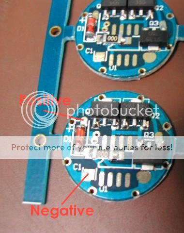
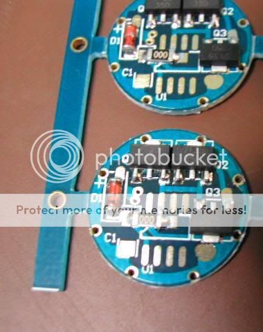
Hi, I just receive my circuit from DealExtreme but doesn´t know where to solder the wires to the led. This circuits are differents from the pictures in the DealExtreme website, so i´m lost here.

7135.jpg


Thanks for any help

Daniel.
 

KrisP

Enlightened
Joined
May 13, 2007
Messages
331
Location
Melbourne, Australia
I received these instead of the 1400mA ones :(

I soldered the positive to the contact of the diode where the + sign is near and the negative to the long pad not completely coated with solder near Q3.

The layout is similar to the multimode board shown below.
 
Last edited by a moderator:

chimo

Flashlight Enthusiast
Joined
Sep 16, 2004
Messages
1,905
Location
Ottawa, Canada
This one's a little different than the 1-4 AMC7135 populated boards. It appears to have a pad for an IC (likely a microcontroller (U1)). In that configuration it would be similar to the PICoPOP or FLuPICs.
 

KrisP

Enlightened
Joined
May 13, 2007
Messages
331
Location
Melbourne, Australia
I did have an image in my above post of the same board with the IC for the multi-levels but for some reason the picture was removed by dano.
 

ardo

Newly Enlightened
Joined
Sep 7, 2007
Messages
23
I did have an image in my above post of the same board with the IC for the multi-levels but for some reason the picture was removed by dano.
I could REALLY use that removed picture. I just got my 1050 boards from DX, and don't want to mess up my very 1st mod!
 

jayb79

Newly Enlightened
Joined
Feb 11, 2005
Messages
167
Location
Exeter ,NH
I did have an image in my above post of the same board with the IC for the multi-levels but for some reason the picture was removed by dano.


From the rules:
"In addition, DO NOT hotlink the images!!! Hotlinking is when you are stealing the bandwidth of a website that you do not have permission to link to."

Save the photo then put it on a free site like imageshack or photbucket.

Hope this helps.
 

Yenster

Newly Enlightened
Joined
Sep 12, 2007
Messages
172
Location
Texas, USA
Was this the picture that got removed?
original.jpg

I believe these boards are only designed for 3xAMC7135 (not 4) and they are different than the product pictures shown on DX. Even though your board doesn't have the IC chip (for multi-modes), it's still wired the same.
 
Last edited:

ardo

Newly Enlightened
Joined
Sep 7, 2007
Messages
23
Indeed, my boards look like the picture in the 1st post, but I'll take your word & wire them up the way you showed. Thank you so much! :thumbsup:
 

TorchBoy

Flashlight Enthusiast
Joined
Jan 15, 2007
Messages
4,486
Location
New Zealand
That's a nice way to use the same board - clever people these board designers. If you want a multimode board use the IC and capacitor, if a single setting is all that's wanted, use a zero value resistor/wire link instead.

The old 3xAMC7135 board only had one chip connected but allowed easy switching in of the extra two chips using solder bridges. Does this new version?
 

ambientmind

Enlightened
Joined
May 8, 2007
Messages
465
i had the same issue, i made a support ticket with them and this is what they told me. works great!

7135copy.jpg
 

TorchBoy

Flashlight Enthusiast
Joined
Jan 15, 2007
Messages
4,486
Location
New Zealand
i had the same issue, i made a support ticket with them and this is what they told me. works great!
Without having seen this particular board in the flesh... that's the input positive and negative. The output negative will be the little pad just to the right of where "Q3" is written on the board, as shown in the earlier photo of the 5 mode board.

Edit: And as mentioned by KrisP in post 2 above.
 
Last edited:

ambientmind

Enlightened
Joined
May 8, 2007
Messages
465
hmmm...i hope not, thats what they told me from dx...should it still work that way? i have one hooked up with the negative there, and it still works. now i'm confused...:thinking:
 
Last edited:

TorchBoy

Flashlight Enthusiast
Joined
Jan 15, 2007
Messages
4,486
Location
New Zealand
When you say it works great, it seems that direct drive would be great. And bright. Have you tried measuring the current?
 

ambientmind

Enlightened
Joined
May 8, 2007
Messages
465
hmmm...now i feel like an idiot! :shakehead i'll try another one tomorrow with it soldered at q3 and see what happens...
 

TorchBoy

Flashlight Enthusiast
Joined
Jan 15, 2007
Messages
4,486
Location
New Zealand
I've just taken a look at one of my triple AMC7135 boards (the old style) and looking at each AMC7135 chip, held so the large ground lug is at the top, along the bottom edge the left pin is the LED negative, the centre pin is ground (ie, input negative) then the right pin is Vdd, the chip input which supposedly uses just 200 microamps.
 

ardo

Newly Enlightened
Joined
Sep 7, 2007
Messages
23
Yesterday, I wired 2 boards with negative from the pad to the right of Q3. It also works great :D - but I also didn't measure the current - Duh...

My contraption is for powering those 53 Led bike lights from DX, and it is a bit of a PITA to take apart to do the measurements. I suppose if I run these until the lights cut off, and if there is no noticeable loss in intensity, I'd assume there is current regulation, is this right?
 
Top