
wquiles
Flashaholic
I started planning for this build almost 3 months ago, back on March 13 of 2009, when Javier proposed a bartering deal of additional hosts in exchange for a super bright light for diving:
https://www.candlepowerforums.com/posts/2876727&postcount=28
Since his offer was very generous, I decided to build two lights instead of one:
- a high power reflectored solution (the one shown in this post)
- a neutral white wide angle (floody) light
The high power one was the more difficult, so I decided to do that one first. Most/all of the lessons learned with that one, should make it easier to do the flood light, since fitting the reflector is fairly time consuming.
I am not calling this a DIY since it was a little bit more involved that prior builds:
- single P7
https://www.candlepowerforums.com/threads/222258
- single MC-E:
https://www.candlepowerforums.com/threads/226575
This particular build has been the longest build I have tried so far, and has taken me over two months to both order and get parts, some of which where not yet available (IMR cells), plus some pending work/proijects on my own "shop". The build was very interesting since there were several questions to consider, including what LED configuration, what reflector to use, what power source, regulated or direct drive (and the efficiency of each solution), etc..
Although I had all of the ideas and steps mentally in my head before I started, I don't pre-plan every single step: I would work on one part, then think how I want to do the next one, sometimes trying something and then abandoning it for something else (here you see only the steps that worked out, otherwise it would have been even more photos for the rejects!).
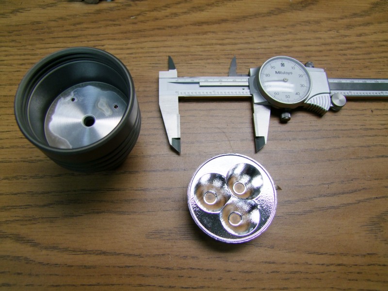
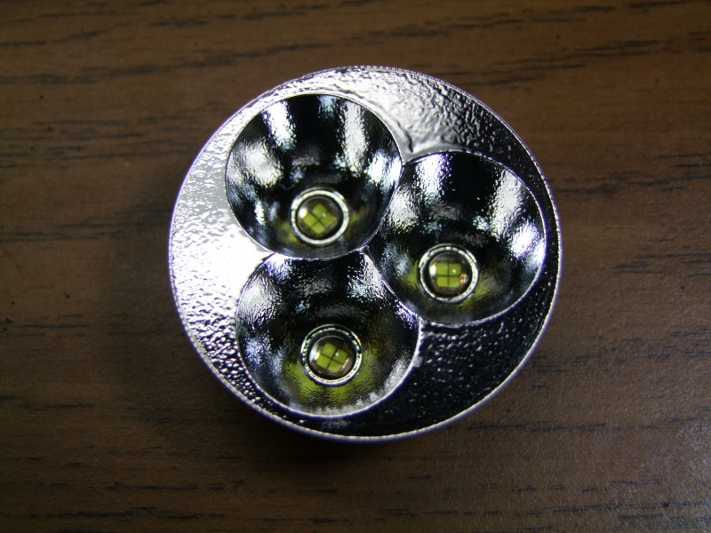
For this solution, I had seen a reflector that I felt would work great, so I started by ordering a triple reflector from Deal Extreme in Asia:
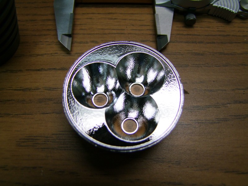
Of course the reflector does not fit on the head (too wide), but it seemed to focus well with a couple of the LED's I tried, so I decided to try ordering some MC-E's to see how it could work. Since Javier said he wanted something really bright, I ordered "M" bin MC-E's, which of course meant waiting additional time as these came from Asia. I still had the challenge of the cells, and how to drive the MC-E's, since the AW LiIon cells have not been available for some time, and the IMR26500 cells were not quite available just yet. I though about using a single A123 cell (two can't fit length-wise in my initial idea), and I even bought an "F" size cell, but it was too wide for the body, so that was eliminated as an option.
The challenge was that I want to deliver about 2.8-3Amps to each emiter, but I only have either 1x or 2x LiIon cells to work with. I wanted a higly efficient solution for the power source, and although I love the hipCC (and I will be building some current regulated Barbo lights using this driver in the fture), the hipCC is a buck driver maxed at 2.8A, so nothing was working out well to power the LED's at max.
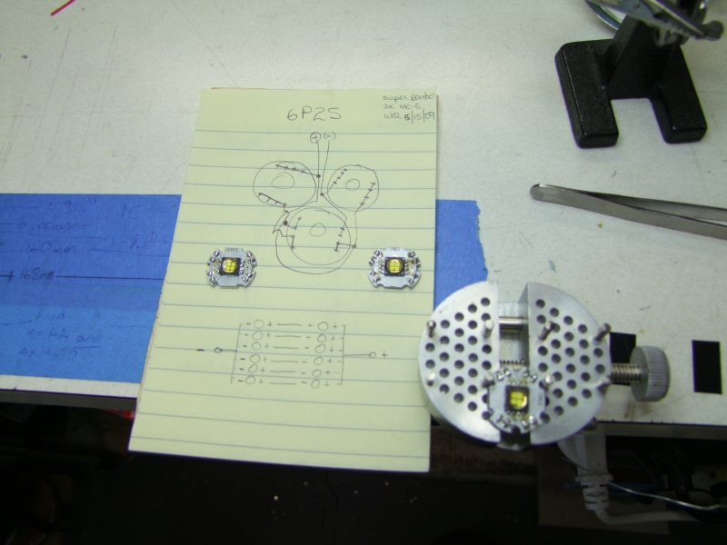
Nothing seem to work until I saw a post from forum member Techjunkie, who had tested 3x MCE's from two IMR cells, in a 6P/2S arrangement. He tested the DD (Direct Drive) solution, but even at this large current load, the IMR cells did not sag, so he had to add high power resistors in series (two 0.47 Ohm in parallel) to bring the current to a "reasonable" level, specially if the 3x MC-E were wired in 6P2S - nominal current was around 4.2 Amps, which is within reason, but still too high for a regulated driver at high efficiency levels. Thanks to his help I was able to move on with the project, and that is the actual configuration that I am using here, which starts at about 88% efficient at 4.5Amps, and gets more and more efficient as the batteries drain. Thanks much Techjunkie")
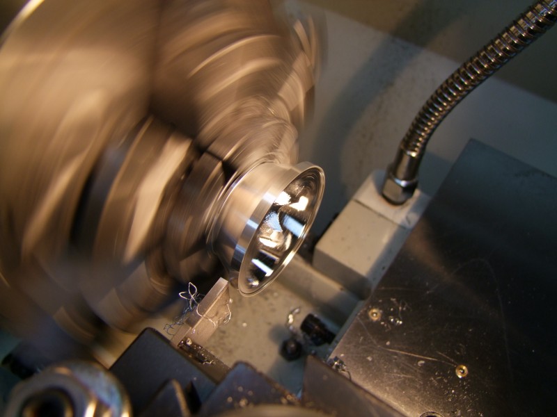
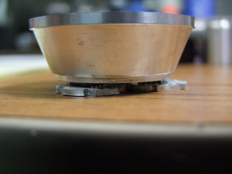
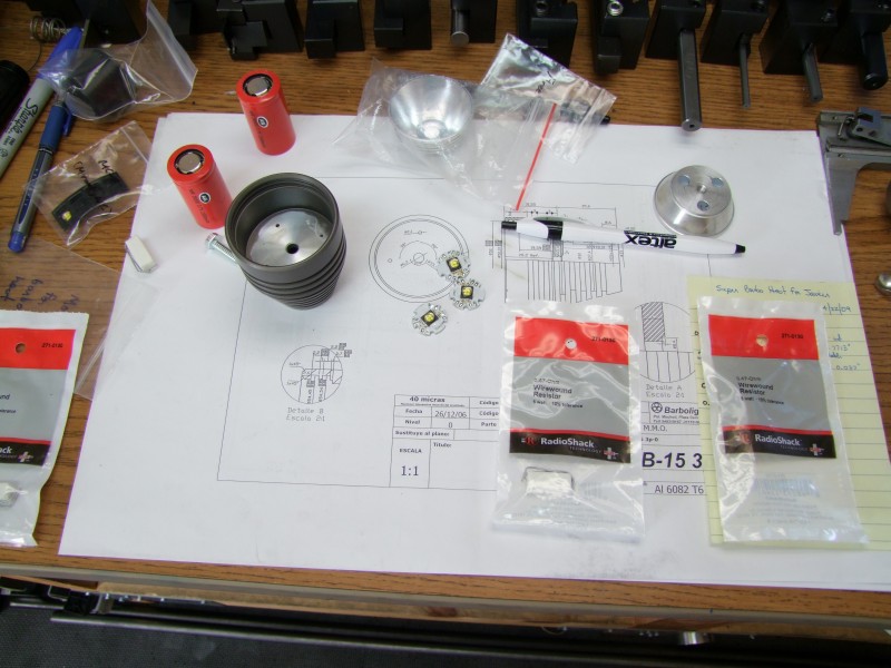
Once the IMR cells arrived from AW, I had all of the piece parts to work on the project, so for the last 2-3 weeks I have been "putting" together Javier's special light. I started by modifying the reflector so that it would fit on the head:
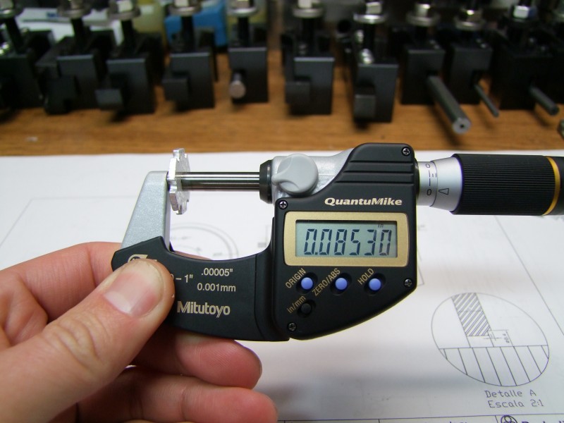
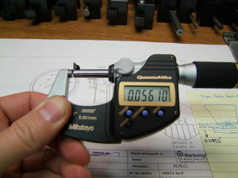
The reflector is kind of deep, and once you put the emiters in place, the overall height would not allow the lens to fit. On top of that, to give me more room to wire the emiters in the required serial/parallel mode, I decided to use a star, which added 0.085" in height:
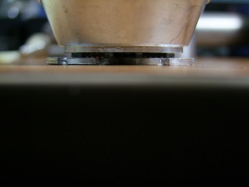
Here is additional height by the emiter itself:
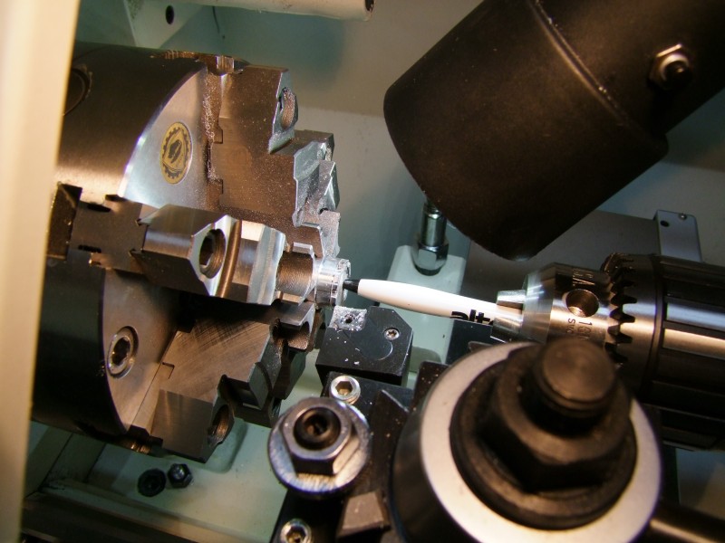
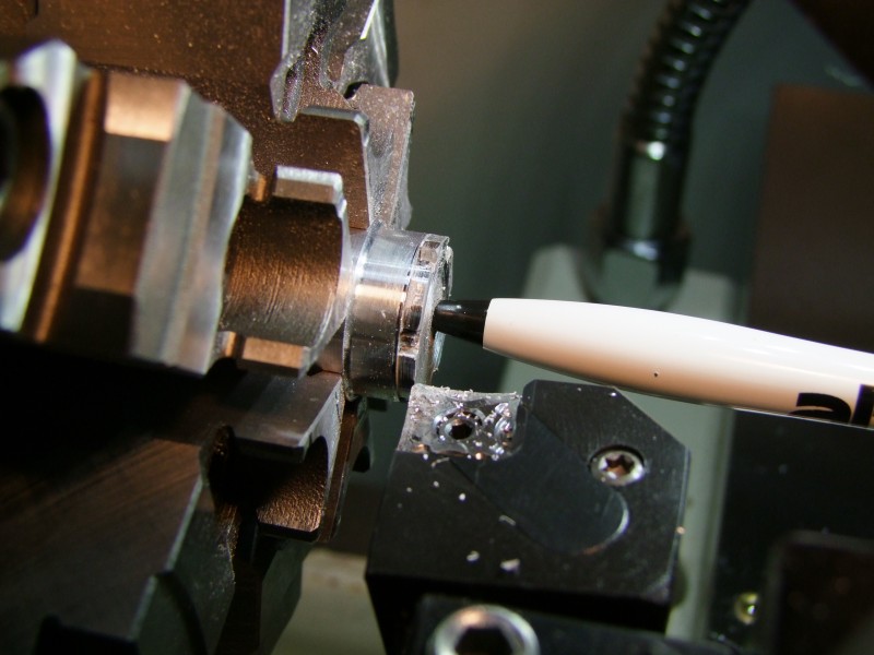
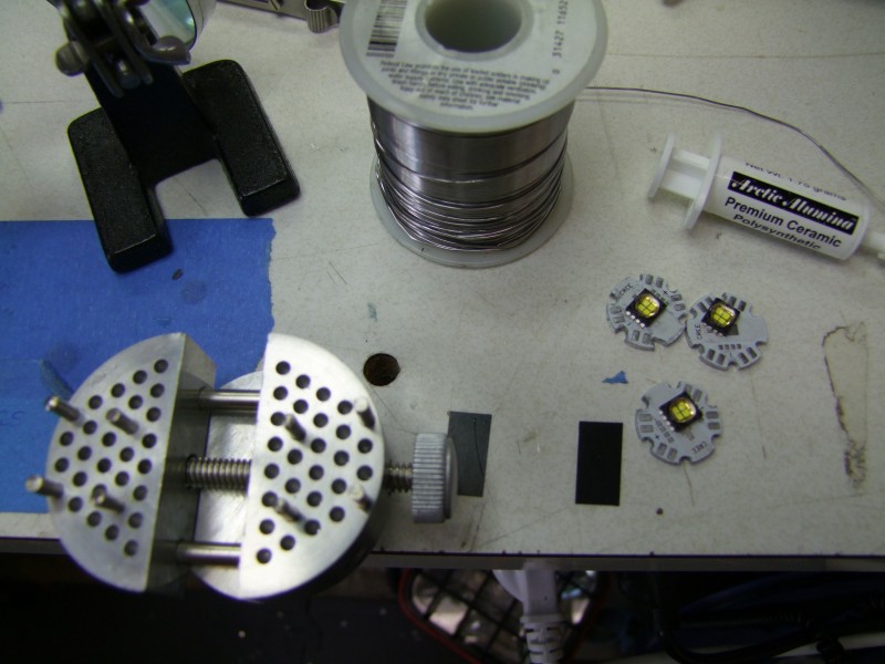
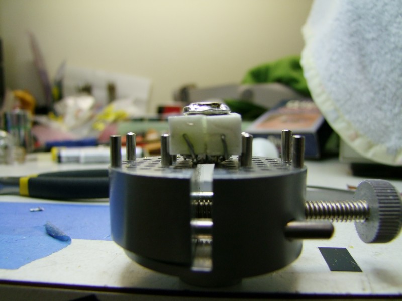
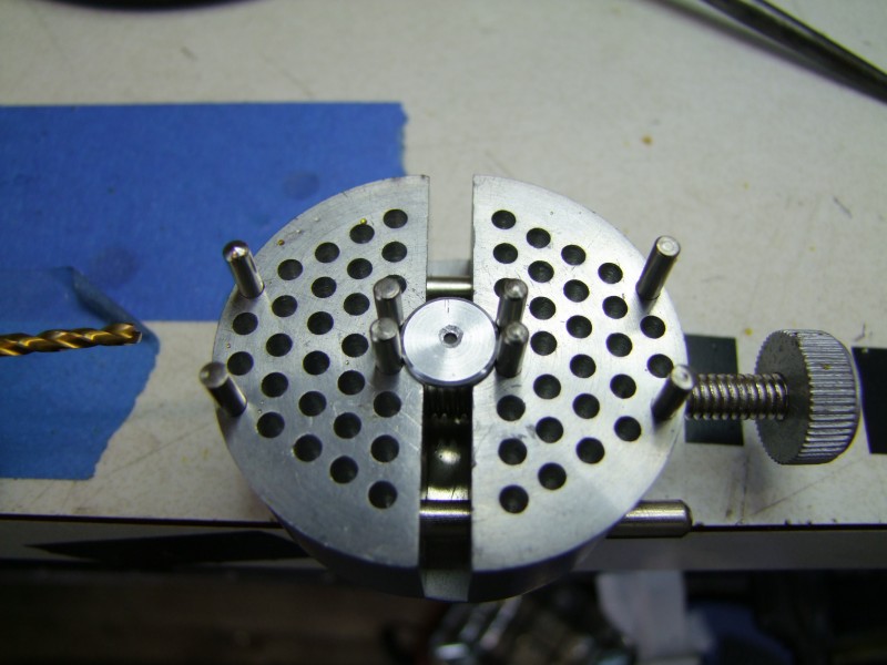
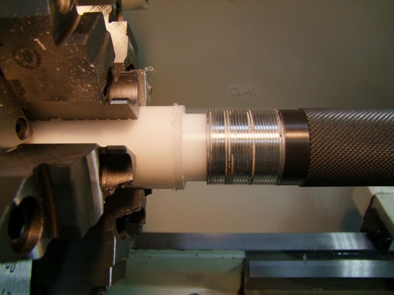
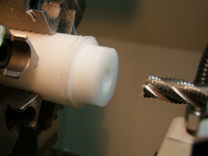
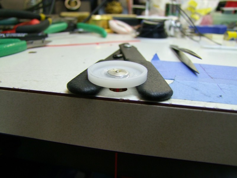
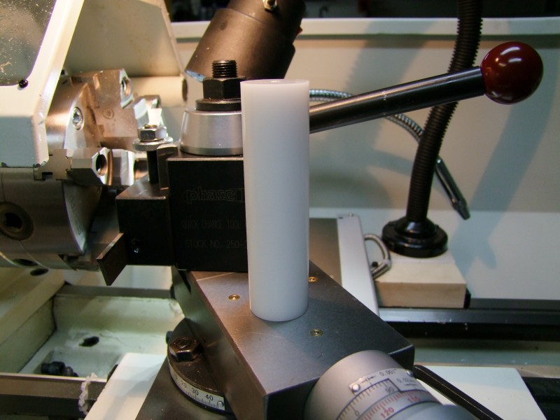
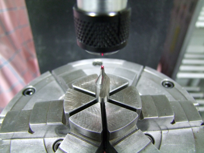
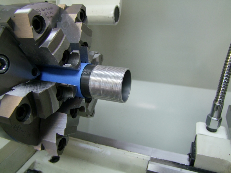
Although I will for sure had to do some boring to take away some of the metal on the built-in heatsink in the head (more on that below), I decided to make the star a little bit thinner – the less metal taken from the head the better. To do that and not damage the wiring/soldering side of the star, I created a small "holder" for the star:

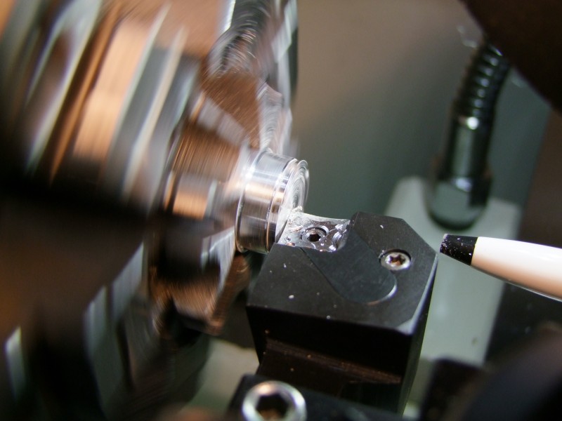
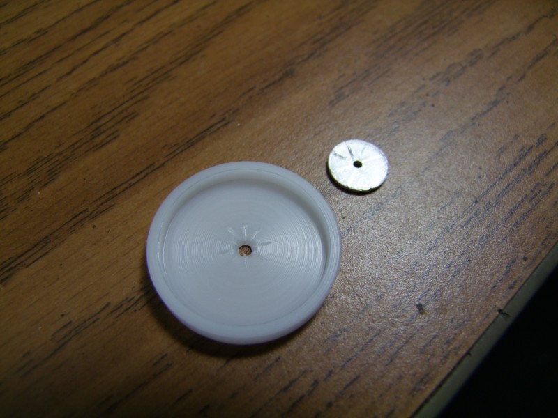
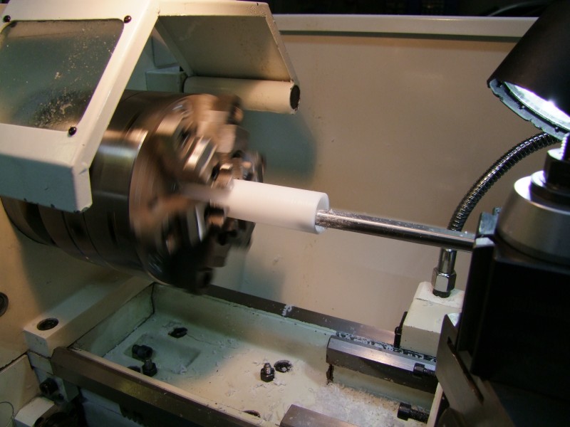
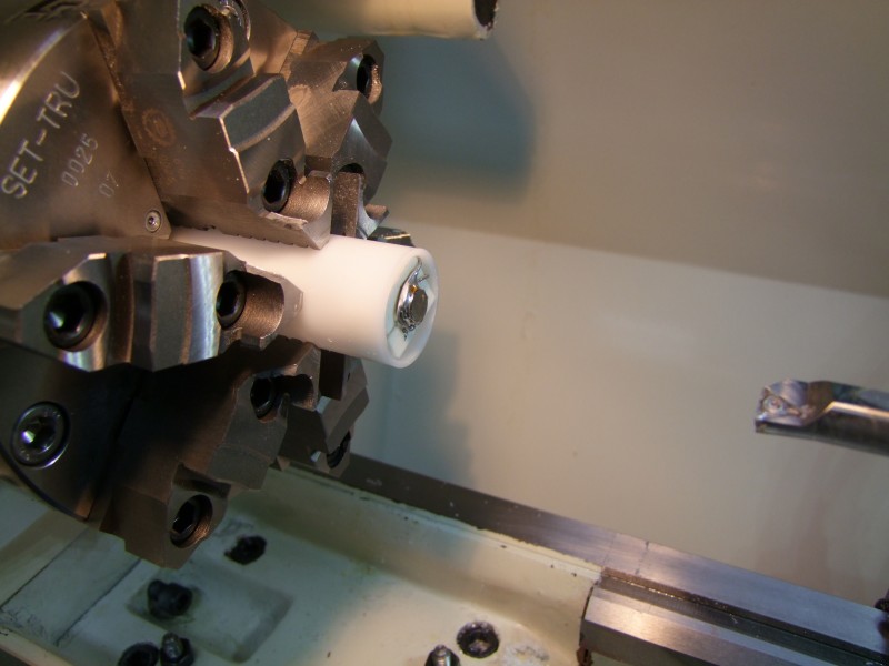
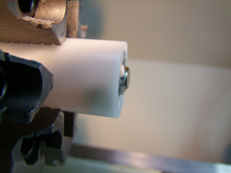
and I used my lathe and sand paper on a granite surface to take about 0.015" from the star:
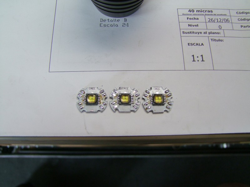
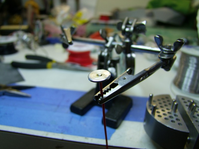
Once I got the stars thinner, I tested the overall solution, which worked as I had hoped (emiters not sanded flat yet in these pictures):
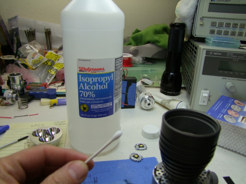
So I soldered the emiters:
I also did grind away some of the edges since they need to be fairly close to each other, and I do not want to remove too much metal on the head close to edges:
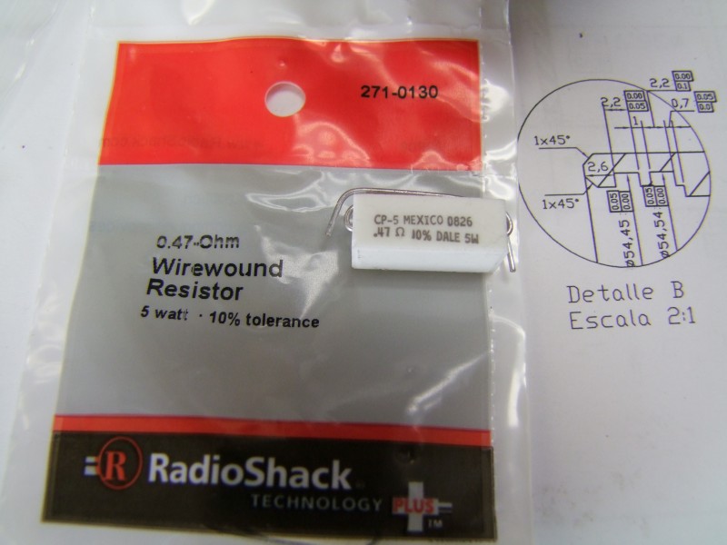
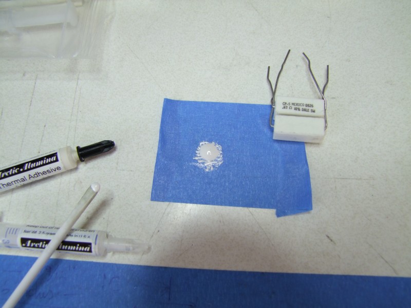
I got the two 0.47 Ohm resistors from Radio Shack:
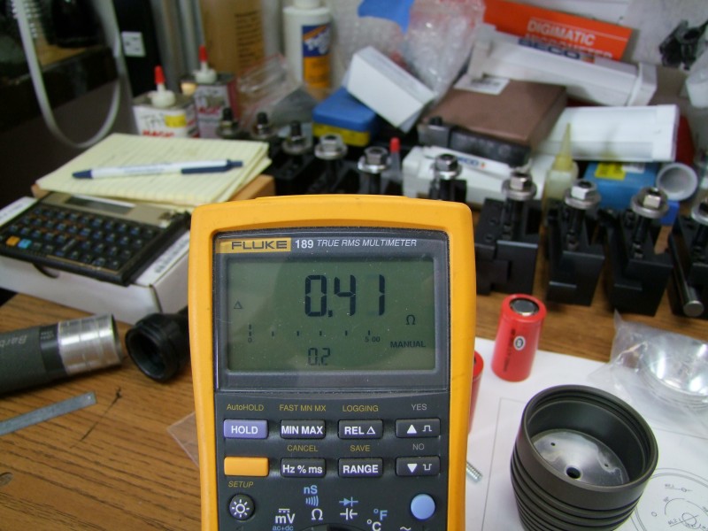
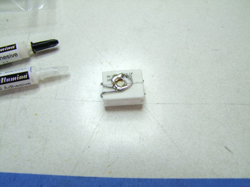
I used thermal epoxy on them, and soldered the two in parallel:
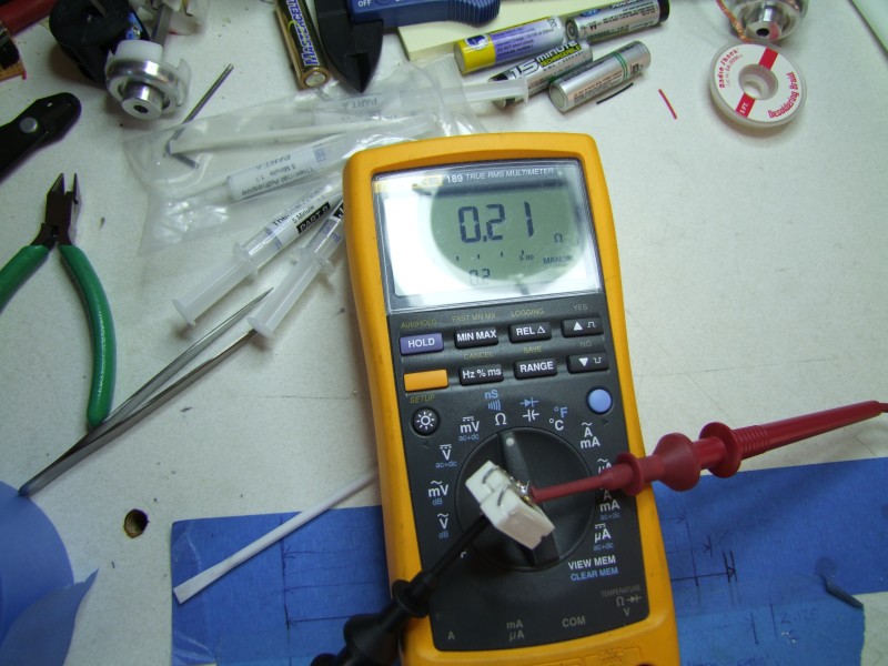
I got about 0.21 Ohms (after taking in consideration the resistance of the probes themselves):
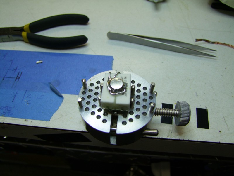
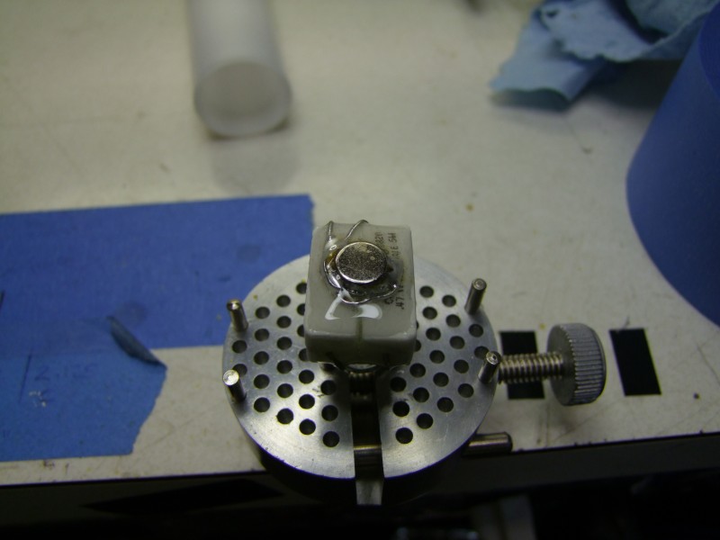
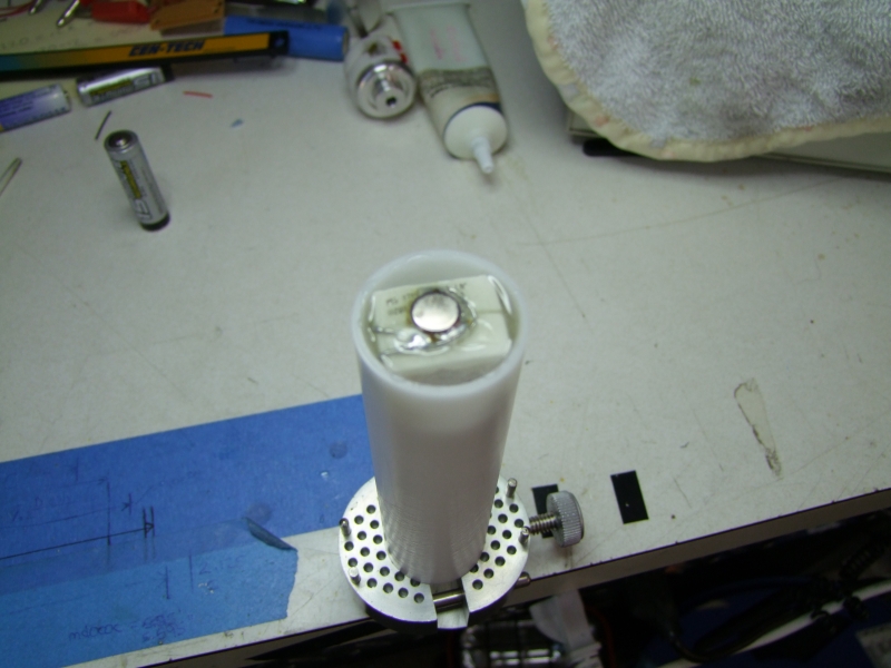
I used epoxy and a metal cup to provide electrical connectivity – this side faces the inside of the tailcap:

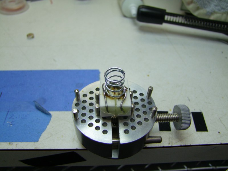
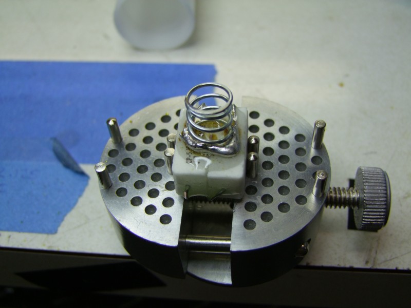
The other side gets a spring (I decided to make the spring part of the battery carrier for several reasons, including allowing the host to be used with other future battery/driver options):
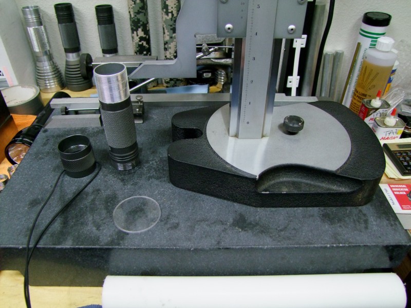
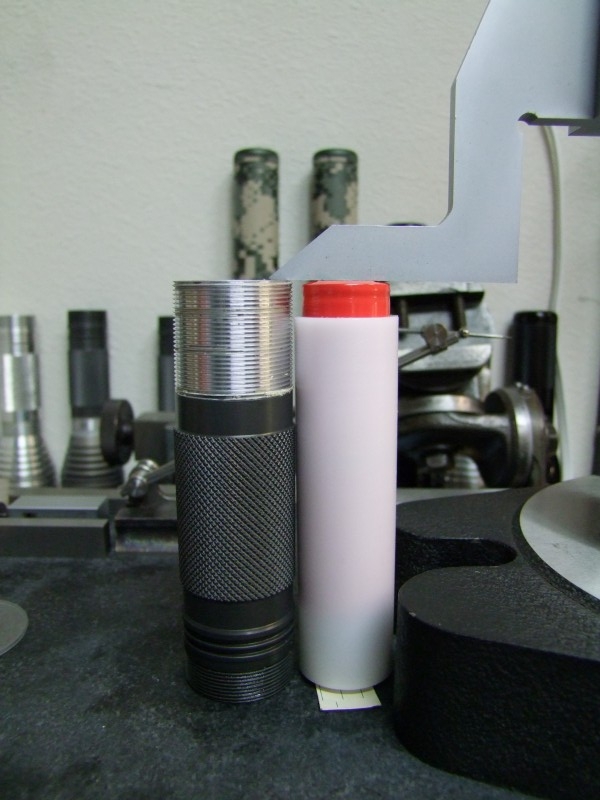
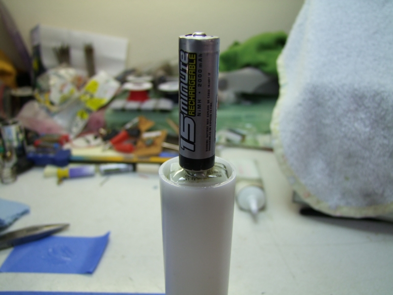
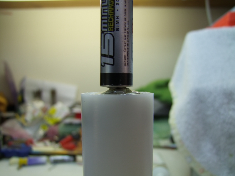
Here I am testing the overall height of the "battery" pack (still lacking the outer delrin sleeve) on my "gigantic" Starrett height gauge:
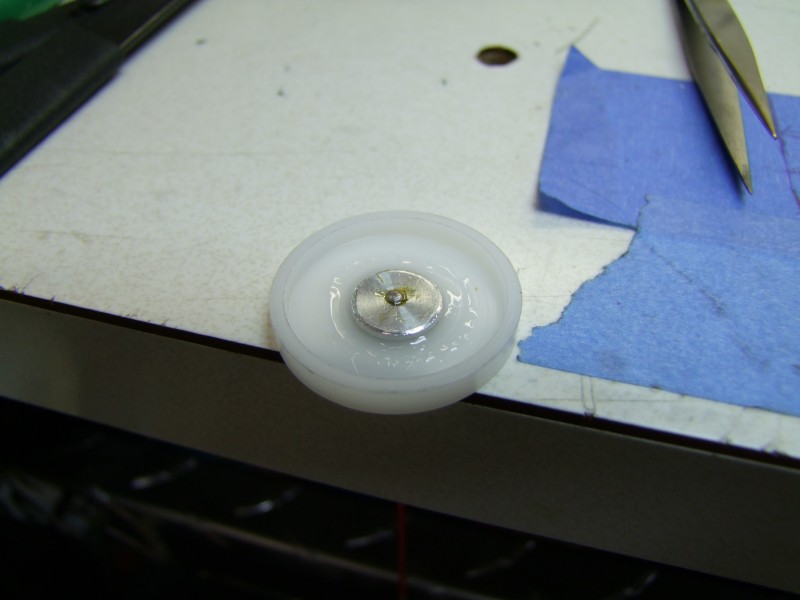
For the positive side of the battery, I am making a new positive contact out of Al, which will be housed in a delrin spacer, to provide electrical isolation:
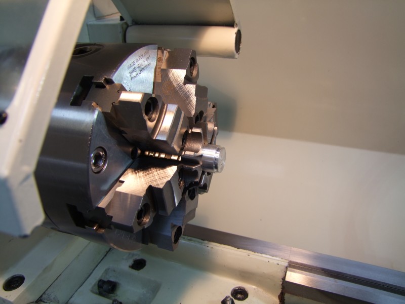
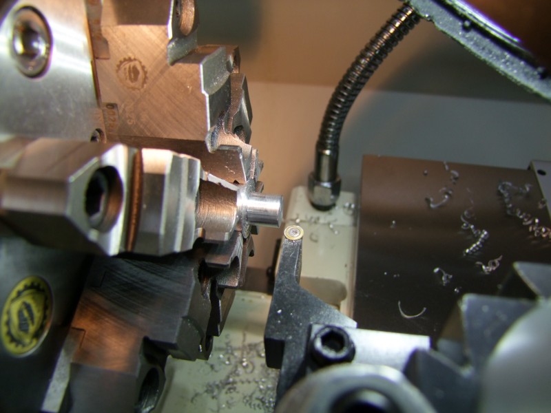
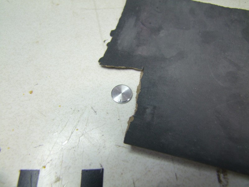
I then drill and chamfer to get the electrical connection:
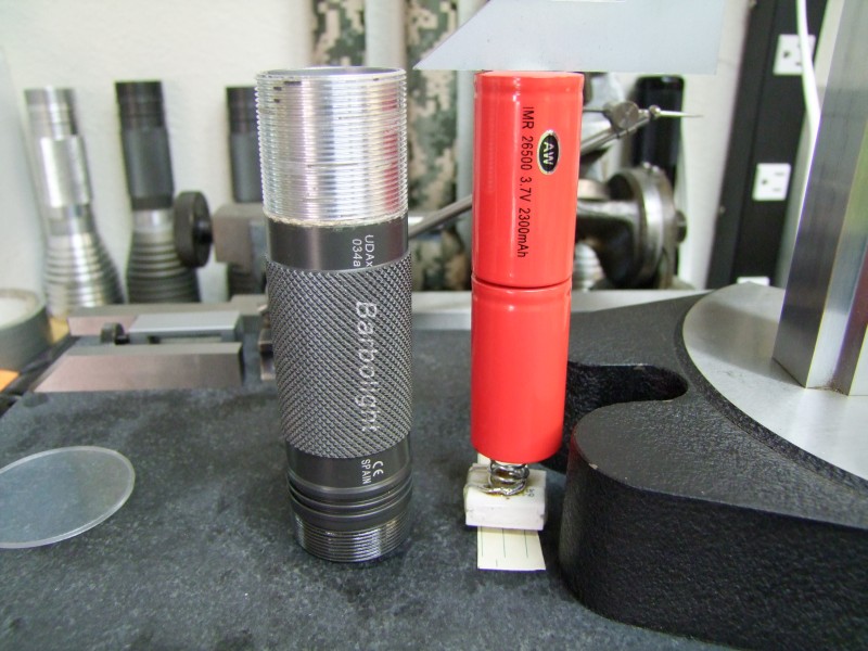
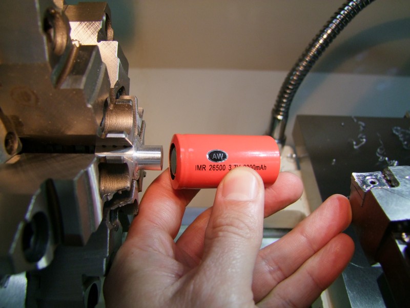
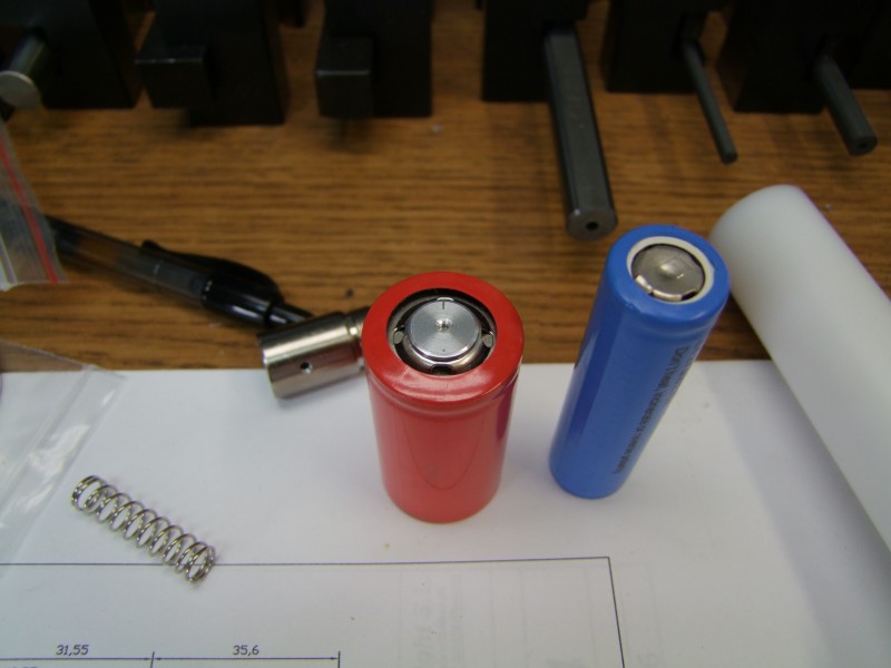
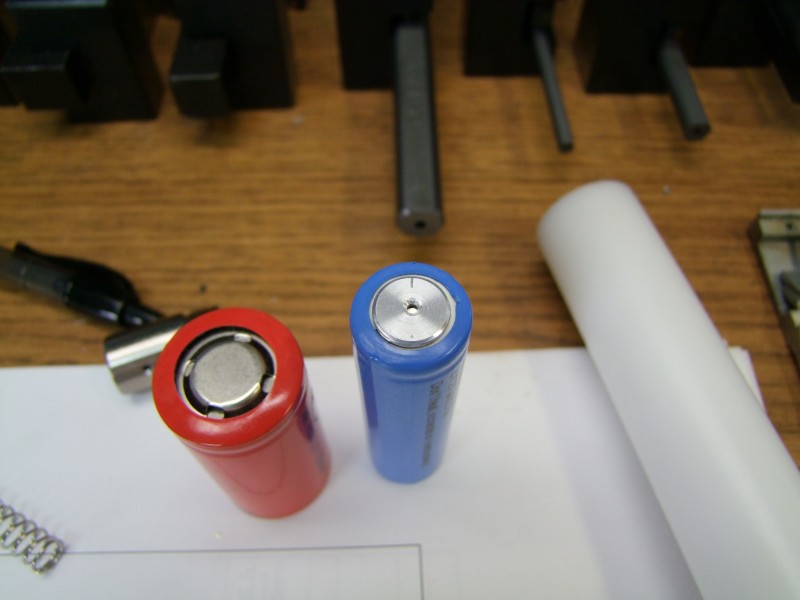
This is how it looks like size-wise compared to both the IMR cell and the 18650 cell (I wanted to make sure the positive contact would work with various future/different cells):
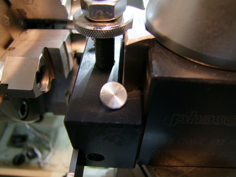
I then proceeded to work on the delrin spacer for the positive contact:


I gave both surfaces some deep scratches so that the epoxy would have some "mechanical" strength to prevent rotation from pulling the two apart:
I then got the positive wire connected – solder on both sides, very tight for a firm connection:
I then epoxied the two pieces:
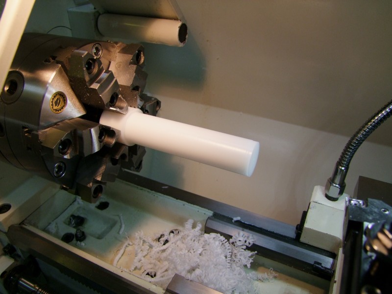
I then started work on the delrin battery sleeve:

For the power resistor, I made a shelf inside the battery carrier to limit its travel. Here is how it looks like:
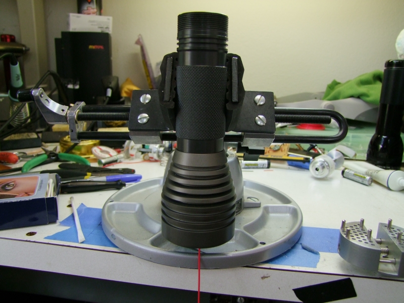
Here is now how the assembled battery pack looks like, next to the host:
I then applied additional epoxy to the resistance module:
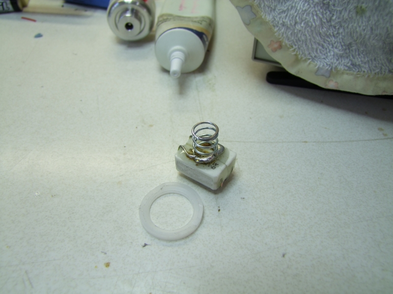
and created a delrin ring that goes on the inside of the battery carrier to keep everything aligned while I epoxied the resistor module to the end of the battery pack - the whole goal was to make everything solid and 100% reliable, in case the light was hit/dropped/etc:
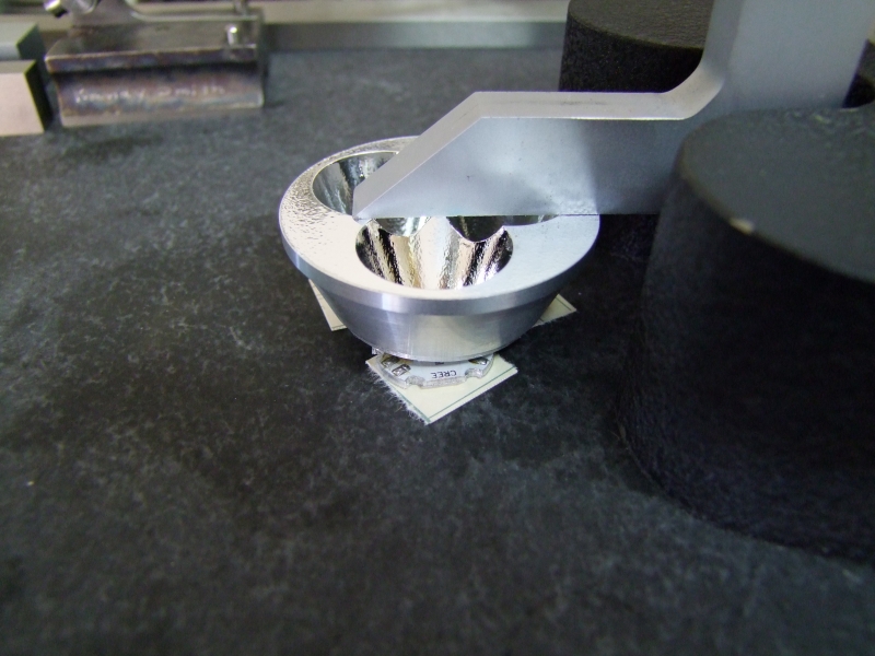
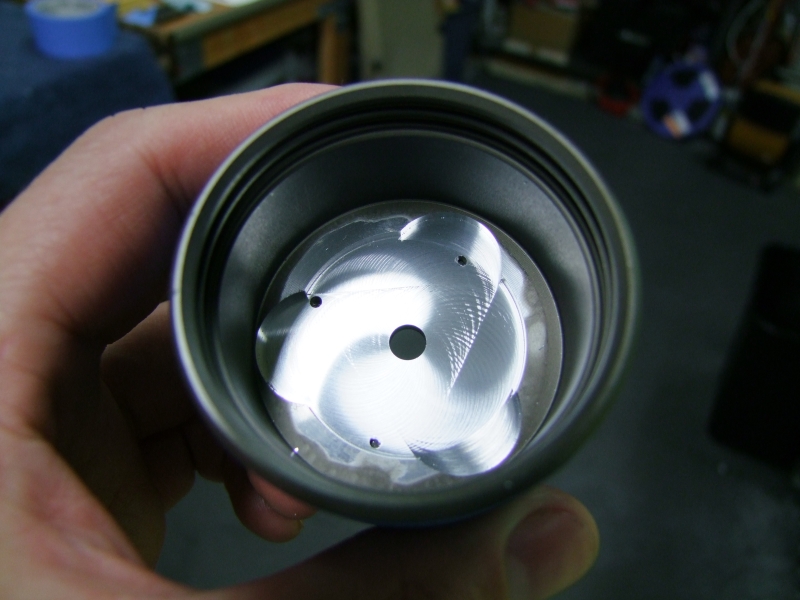
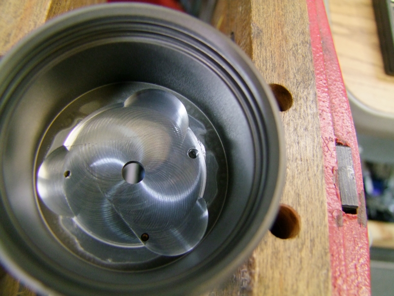
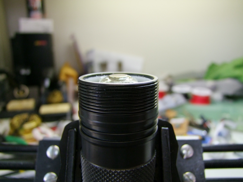
Back to the reflector/emiter combo, I am once again checking how much I have to remove from the head:
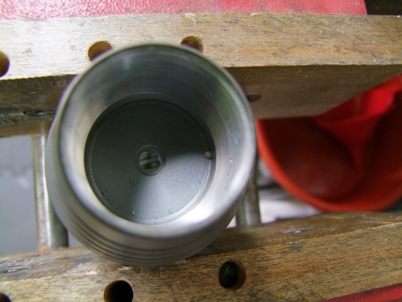
So I start work on the head:
Since I have the original drawings for this host as Javier made available last year, I know how much metal and where not to cut, so this was as most as I felt comfortable cutting without weakening the head. However, as you can see, it is not quite enough to get the emiters to fit:
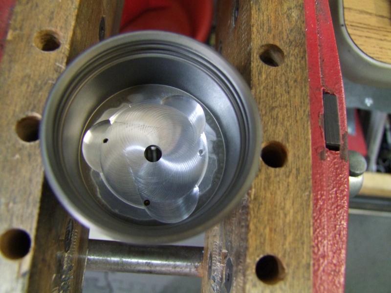
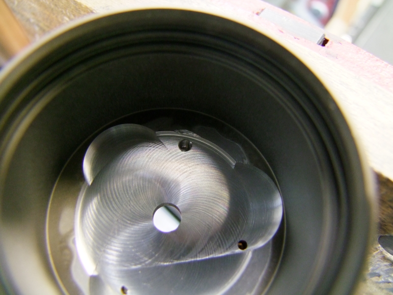
So I set my mill to do some more cutting:
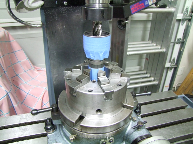

and this is how it looks now:
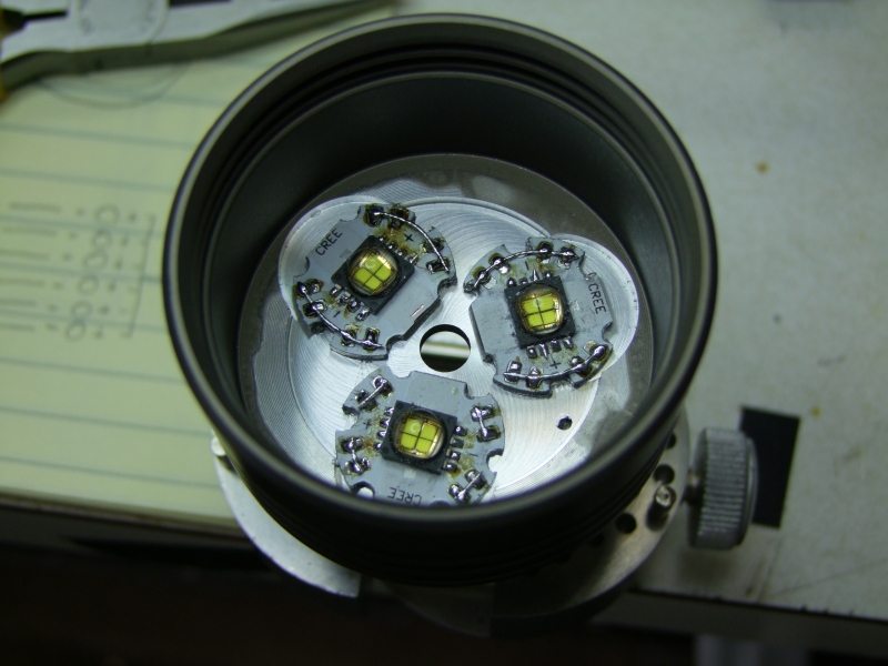
and the emiters now fit:
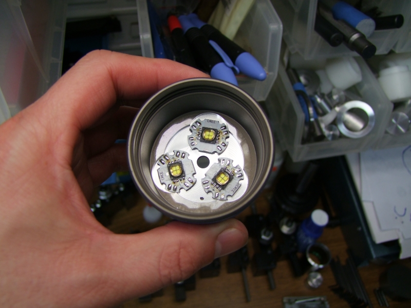
and after a dry assembly, everything fits as I expected:
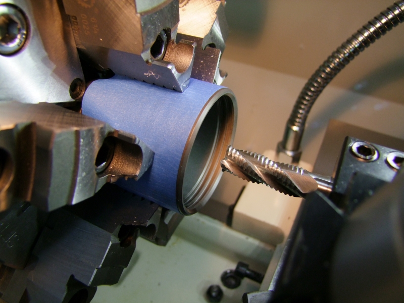
Back to the emiters, I started the soldering for the pairs that will be in parallel and in series:
I then drill and tapped one of the smaller existing holes, which will become my solid electrical negative contact:
I used my Dremel tool to cut a small relief for the screw:
and this is how it looks like (dry fit – no epoxy yet):
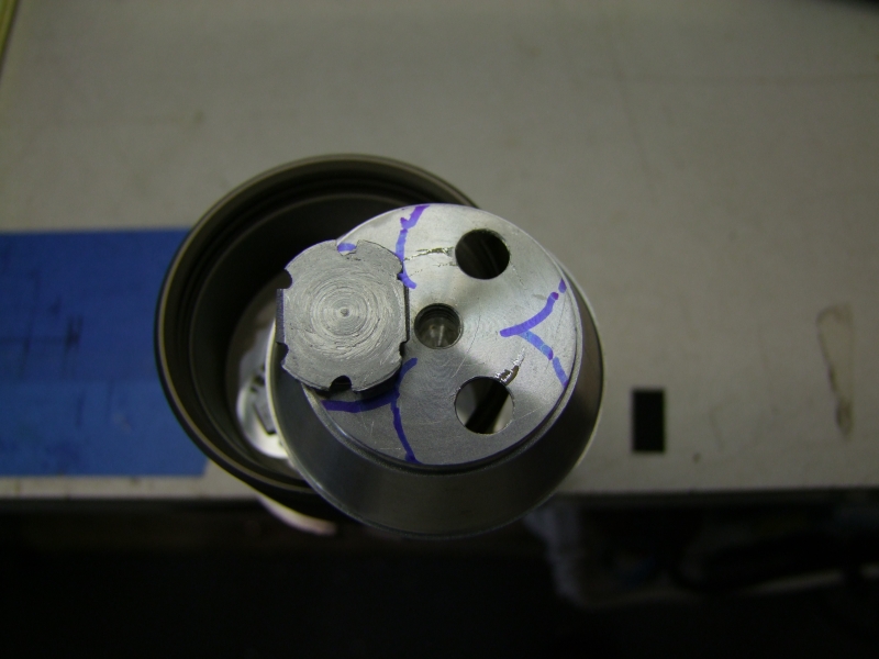
I marked the back of the reflector to know where to apply the epoxy that will keep the reflector in place:
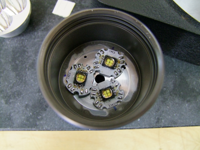
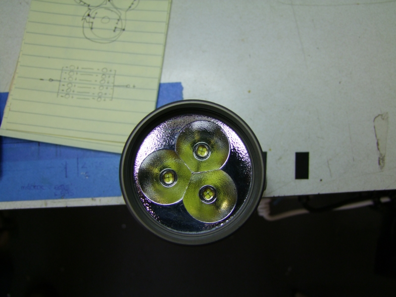
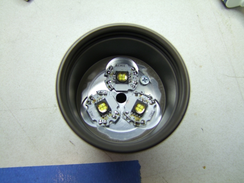
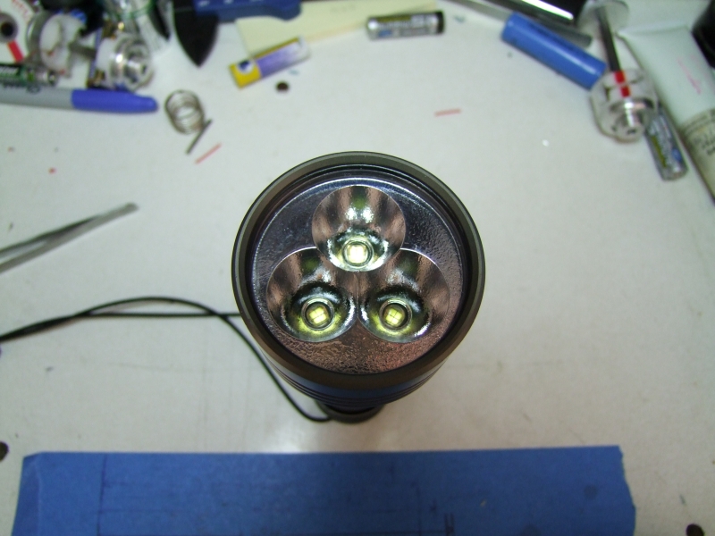
and I use thermal epoxy to glue the emiters to the head, while using the actual reflector to center the emiters in place:

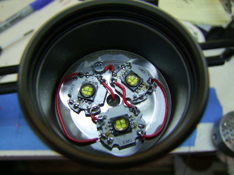
and here is the head with the emiters perfectly centered:
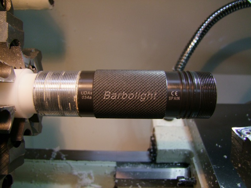
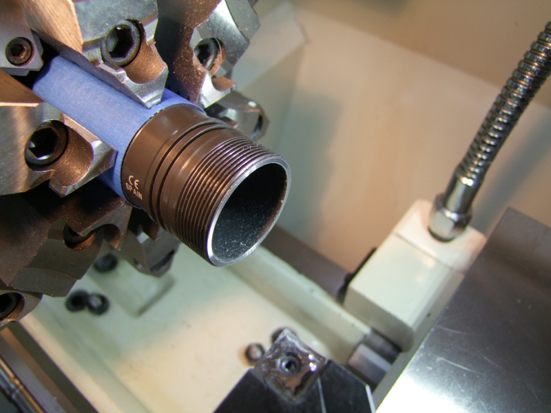
Back on the lathe, I cleaned up both ends of the tube, specially removing the anodizing on the tailcap side for a good electrical contact:
Before seating the positive contact, I gave both surfaces some scratches to help the epoxy have a mechanical bond:
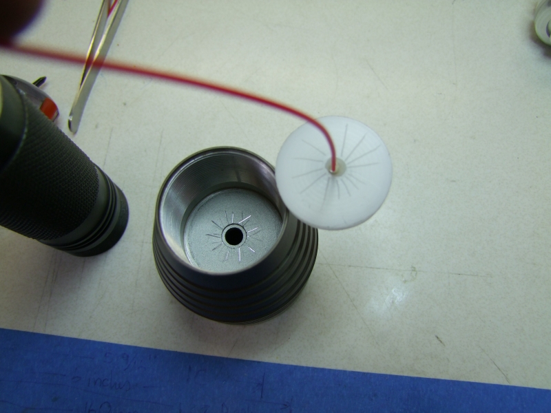
The body itself centers and keeps the positive contact aligned – it is just a very light friction fit:
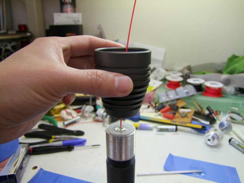
Then use the battery pack to apply some pressure while the epoxy sets:
this is how it looks like once everything is dry:

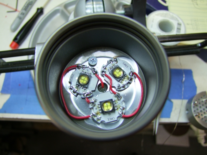
Once set, I can proceed to wire the emiters:
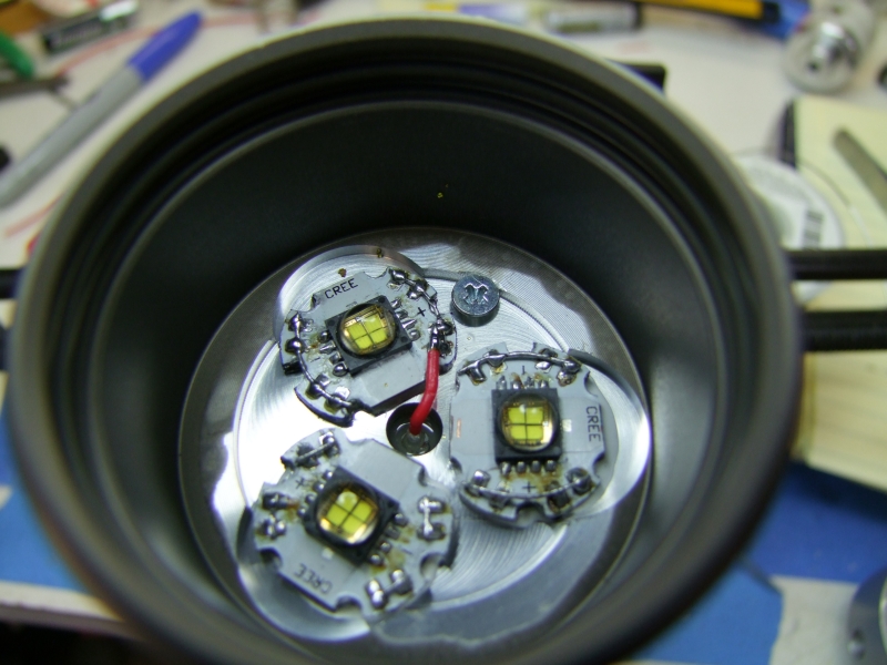
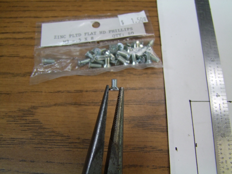
Here is the screw and negative contact wire:

All wired up:
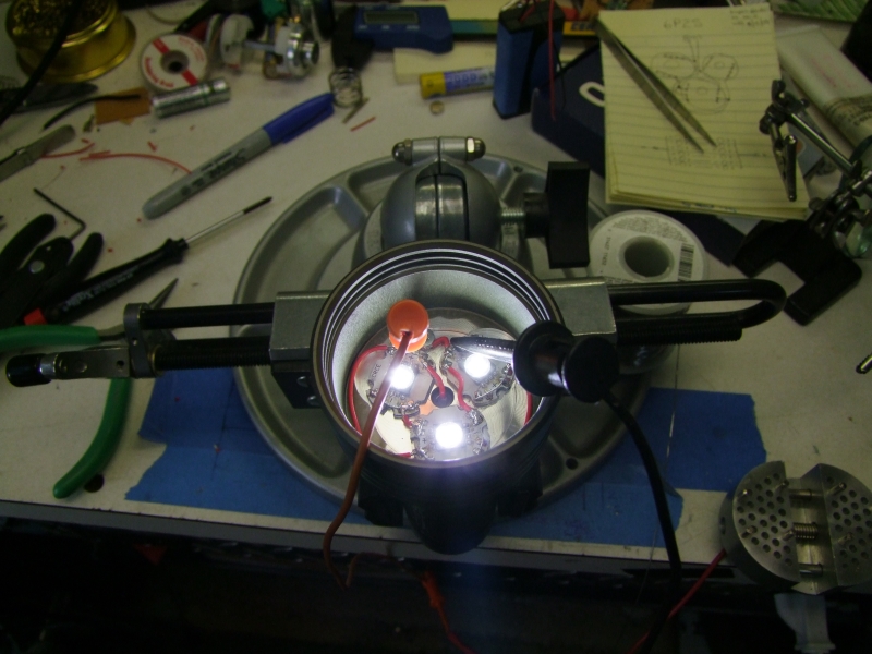
And then, the test with the bench supply, first at about 100mA:
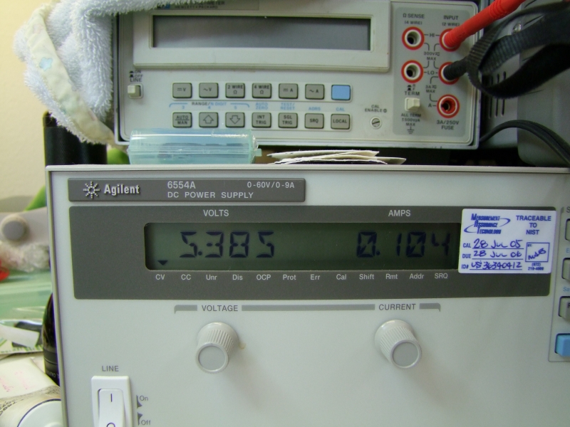
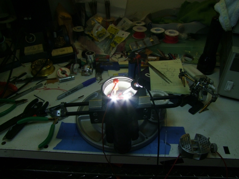
then about 1Amp:
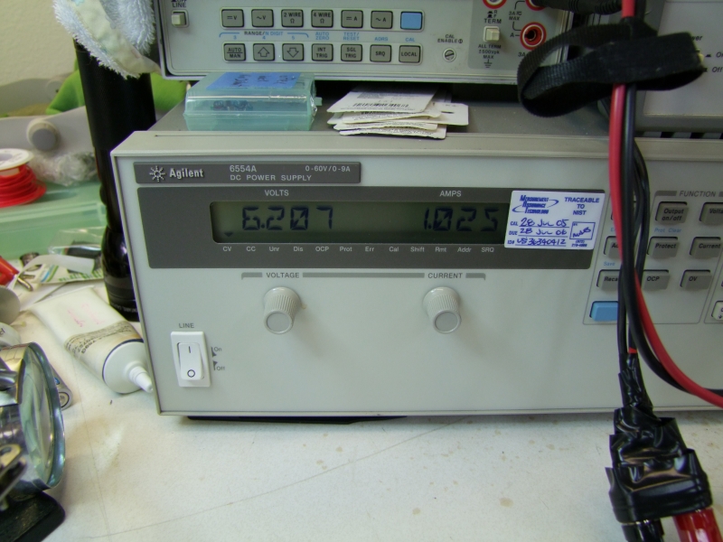
about 2Amps:
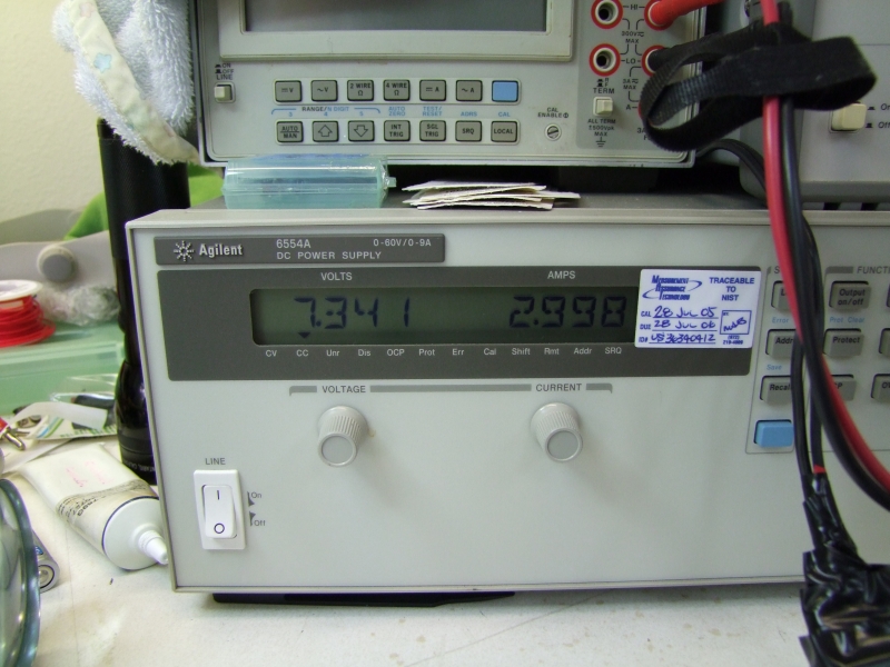
about 3Amps:
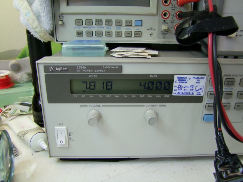
about 4Amps:
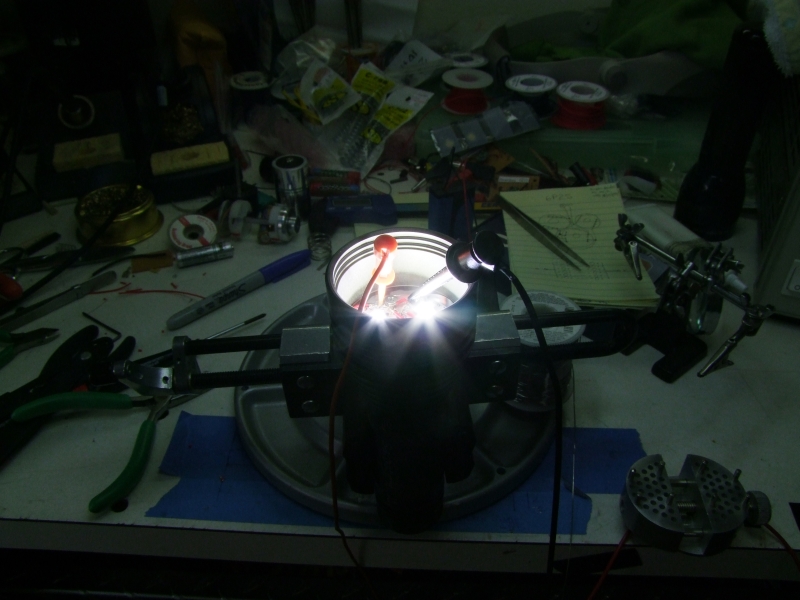
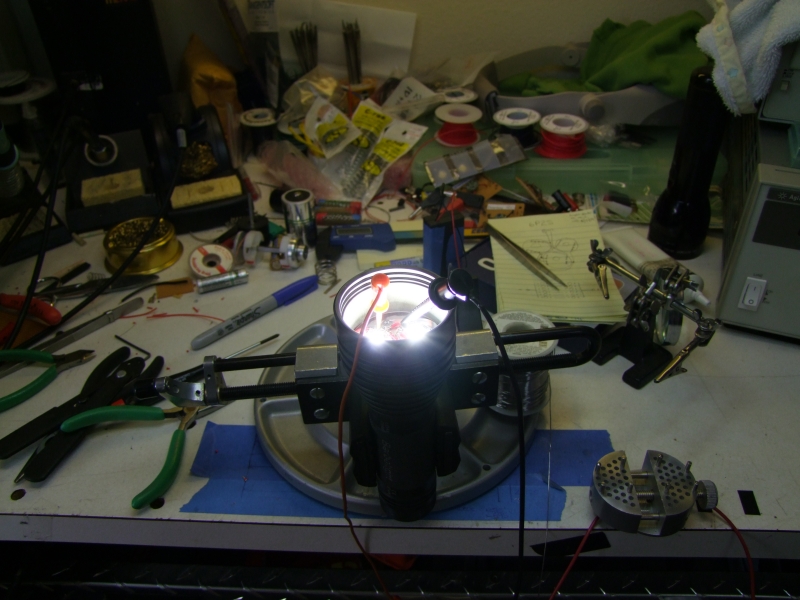
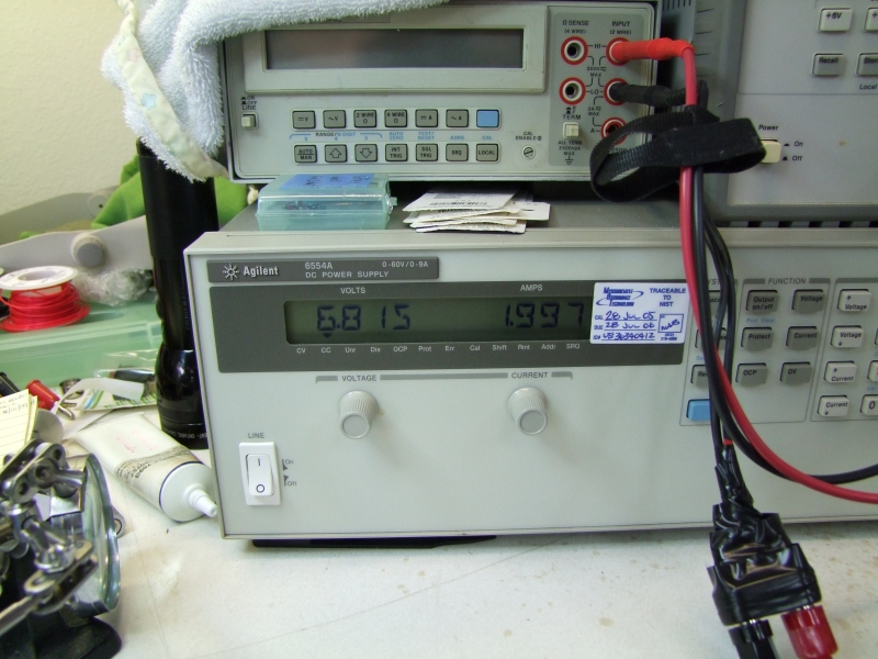
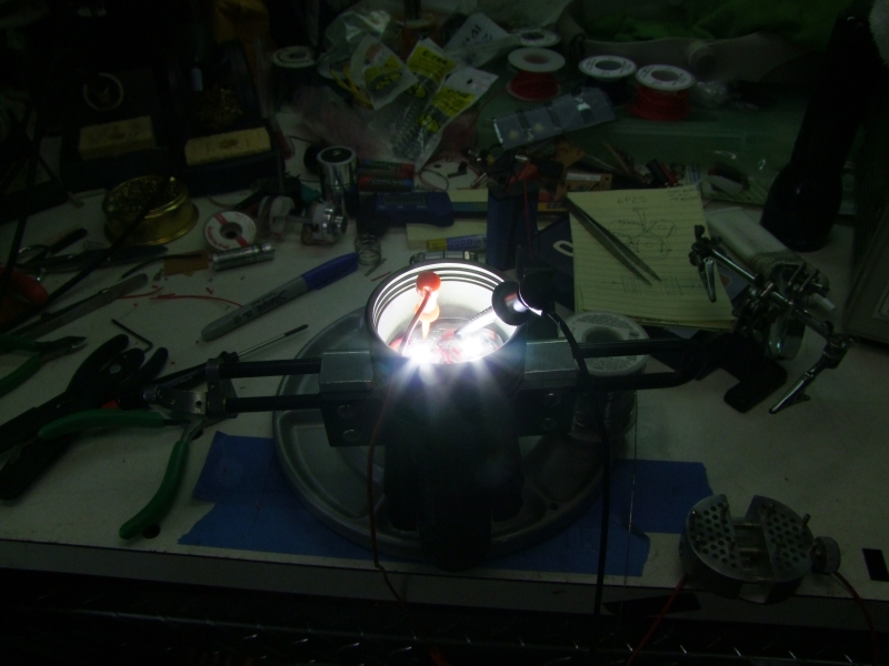
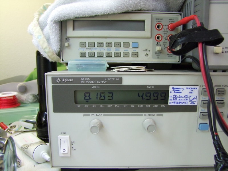
and finally 5Amps:

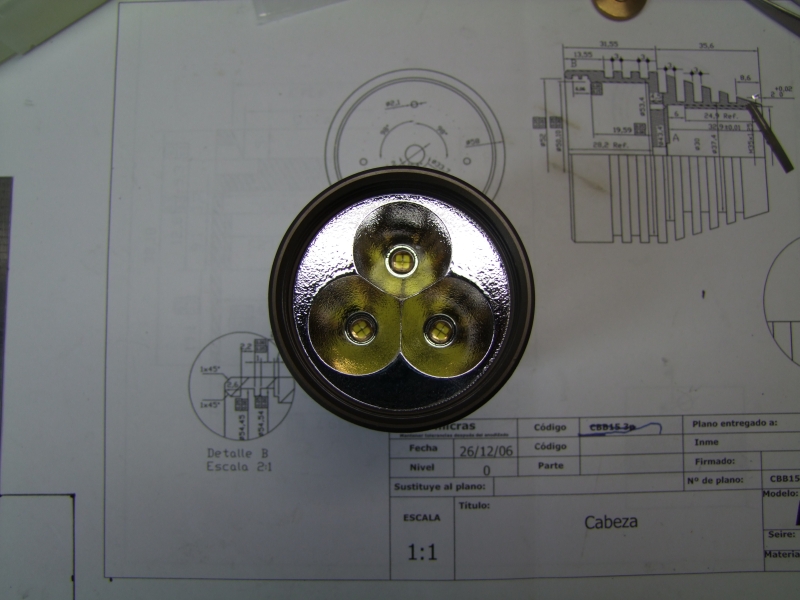
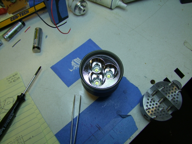
Here is how the beam looks like against the wall – you can see the 3 emiter beams:
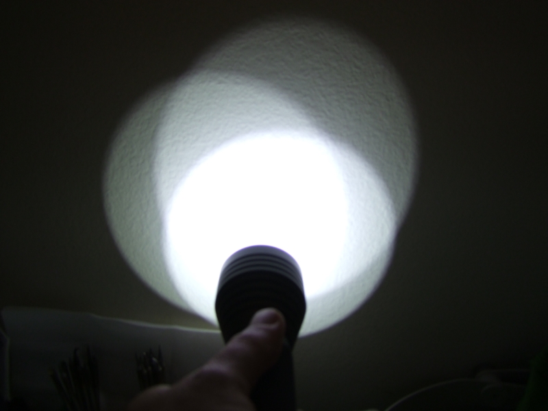
and here is a blended to show how it would look like without reflectors – just a massive flood:
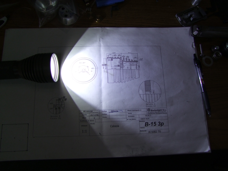
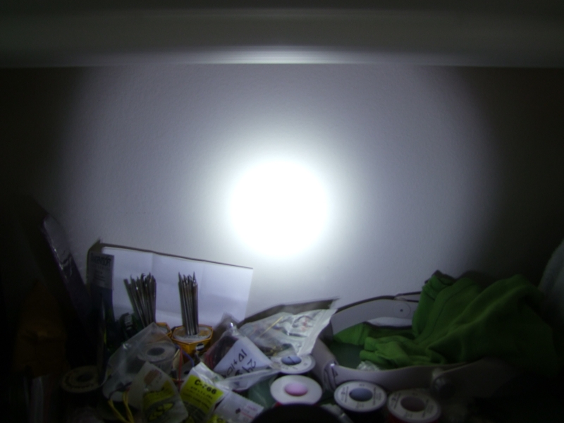
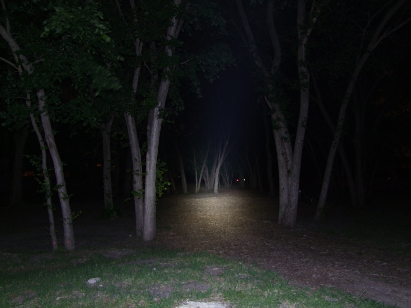
here is the beamshot with the reflector in place – simply awesome!
Here is the assembled light. I just need to add the water-sealing silicone to seal the head and main tube – everything else is complete:
This completes the build. Beamshots below on post #2.
https://www.candlepowerforums.com/posts/2876727&postcount=28
Since his offer was very generous, I decided to build two lights instead of one:
- a high power reflectored solution (the one shown in this post)
- a neutral white wide angle (floody) light
The high power one was the more difficult, so I decided to do that one first. Most/all of the lessons learned with that one, should make it easier to do the flood light, since fitting the reflector is fairly time consuming.
I am not calling this a DIY since it was a little bit more involved that prior builds:
- single P7
https://www.candlepowerforums.com/threads/222258
- single MC-E:
https://www.candlepowerforums.com/threads/226575
This particular build has been the longest build I have tried so far, and has taken me over two months to both order and get parts, some of which where not yet available (IMR cells), plus some pending work/proijects on my own "shop". The build was very interesting since there were several questions to consider, including what LED configuration, what reflector to use, what power source, regulated or direct drive (and the efficiency of each solution), etc..
Although I had all of the ideas and steps mentally in my head before I started, I don't pre-plan every single step: I would work on one part, then think how I want to do the next one, sometimes trying something and then abandoning it for something else (here you see only the steps that worked out, otherwise it would have been even more photos for the rejects!).
For this solution, I had seen a reflector that I felt would work great, so I started by ordering a triple reflector from Deal Extreme in Asia:
Of course the reflector does not fit on the head (too wide), but it seemed to focus well with a couple of the LED's I tried, so I decided to try ordering some MC-E's to see how it could work. Since Javier said he wanted something really bright, I ordered "M" bin MC-E's, which of course meant waiting additional time as these came from Asia. I still had the challenge of the cells, and how to drive the MC-E's, since the AW LiIon cells have not been available for some time, and the IMR26500 cells were not quite available just yet. I though about using a single A123 cell (two can't fit length-wise in my initial idea), and I even bought an "F" size cell, but it was too wide for the body, so that was eliminated as an option.
The challenge was that I want to deliver about 2.8-3Amps to each emiter, but I only have either 1x or 2x LiIon cells to work with. I wanted a higly efficient solution for the power source, and although I love the hipCC (and I will be building some current regulated Barbo lights using this driver in the fture), the hipCC is a buck driver maxed at 2.8A, so nothing was working out well to power the LED's at max.
Nothing seem to work until I saw a post from forum member Techjunkie, who had tested 3x MCE's from two IMR cells, in a 6P/2S arrangement. He tested the DD (Direct Drive) solution, but even at this large current load, the IMR cells did not sag, so he had to add high power resistors in series (two 0.47 Ohm in parallel) to bring the current to a "reasonable" level, specially if the 3x MC-E were wired in 6P2S - nominal current was around 4.2 Amps, which is within reason, but still too high for a regulated driver at high efficiency levels. Thanks to his help I was able to move on with the project, and that is the actual configuration that I am using here, which starts at about 88% efficient at 4.5Amps, and gets more and more efficient as the batteries drain. Thanks much Techjunkie
Once the IMR cells arrived from AW, I had all of the piece parts to work on the project, so for the last 2-3 weeks I have been "putting" together Javier's special light. I started by modifying the reflector so that it would fit on the head:
The reflector is kind of deep, and once you put the emiters in place, the overall height would not allow the lens to fit. On top of that, to give me more room to wire the emiters in the required serial/parallel mode, I decided to use a star, which added 0.085" in height:
Here is additional height by the emiter itself:
Although I will for sure had to do some boring to take away some of the metal on the built-in heatsink in the head (more on that below), I decided to make the star a little bit thinner – the less metal taken from the head the better. To do that and not damage the wiring/soldering side of the star, I created a small "holder" for the star:
and I used my lathe and sand paper on a granite surface to take about 0.015" from the star:
Once I got the stars thinner, I tested the overall solution, which worked as I had hoped (emiters not sanded flat yet in these pictures):
So I soldered the emiters:
I also did grind away some of the edges since they need to be fairly close to each other, and I do not want to remove too much metal on the head close to edges:
I got the two 0.47 Ohm resistors from Radio Shack:
I used thermal epoxy on them, and soldered the two in parallel:
I got about 0.21 Ohms (after taking in consideration the resistance of the probes themselves):
I used epoxy and a metal cup to provide electrical connectivity – this side faces the inside of the tailcap:
The other side gets a spring (I decided to make the spring part of the battery carrier for several reasons, including allowing the host to be used with other future battery/driver options):
Here I am testing the overall height of the "battery" pack (still lacking the outer delrin sleeve) on my "gigantic" Starrett height gauge:
For the positive side of the battery, I am making a new positive contact out of Al, which will be housed in a delrin spacer, to provide electrical isolation:
I then drill and chamfer to get the electrical connection:
This is how it looks like size-wise compared to both the IMR cell and the 18650 cell (I wanted to make sure the positive contact would work with various future/different cells):
I then proceeded to work on the delrin spacer for the positive contact:
I gave both surfaces some deep scratches so that the epoxy would have some "mechanical" strength to prevent rotation from pulling the two apart:
I then got the positive wire connected – solder on both sides, very tight for a firm connection:
I then epoxied the two pieces:
I then started work on the delrin battery sleeve:
For the power resistor, I made a shelf inside the battery carrier to limit its travel. Here is how it looks like:
Here is now how the assembled battery pack looks like, next to the host:
I then applied additional epoxy to the resistance module:
and created a delrin ring that goes on the inside of the battery carrier to keep everything aligned while I epoxied the resistor module to the end of the battery pack - the whole goal was to make everything solid and 100% reliable, in case the light was hit/dropped/etc:
Back to the reflector/emiter combo, I am once again checking how much I have to remove from the head:
So I start work on the head:
Since I have the original drawings for this host as Javier made available last year, I know how much metal and where not to cut, so this was as most as I felt comfortable cutting without weakening the head. However, as you can see, it is not quite enough to get the emiters to fit:
So I set my mill to do some more cutting:
and this is how it looks now:
and the emiters now fit:
and after a dry assembly, everything fits as I expected:
Back to the emiters, I started the soldering for the pairs that will be in parallel and in series:
I then drill and tapped one of the smaller existing holes, which will become my solid electrical negative contact:
I used my Dremel tool to cut a small relief for the screw:
and this is how it looks like (dry fit – no epoxy yet):
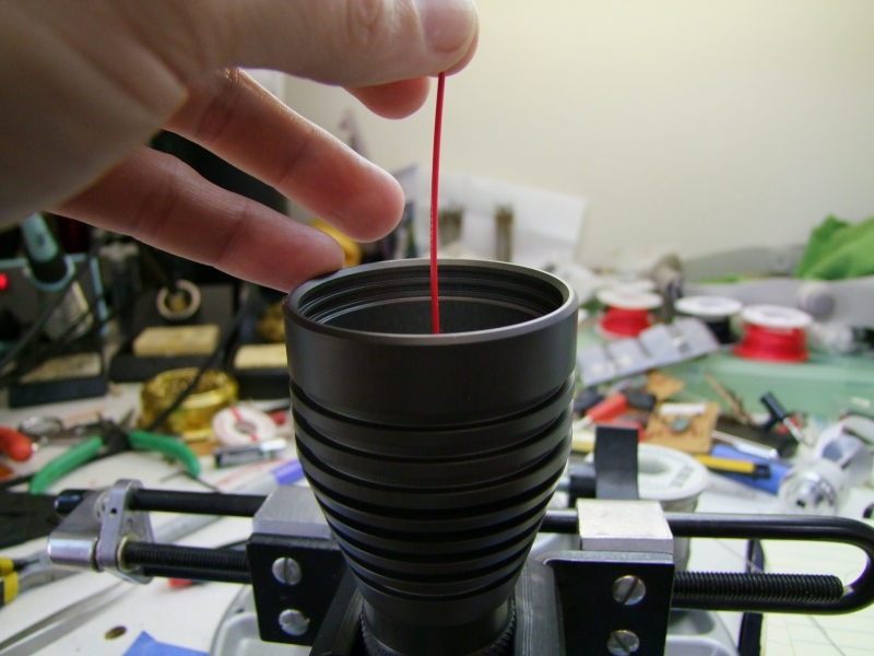
I marked the back of the reflector to know where to apply the epoxy that will keep the reflector in place:
and I use thermal epoxy to glue the emiters to the head, while using the actual reflector to center the emiters in place:
and here is the head with the emiters perfectly centered:
Back on the lathe, I cleaned up both ends of the tube, specially removing the anodizing on the tailcap side for a good electrical contact:
Before seating the positive contact, I gave both surfaces some scratches to help the epoxy have a mechanical bond:
The body itself centers and keeps the positive contact aligned – it is just a very light friction fit:
Then use the battery pack to apply some pressure while the epoxy sets:
this is how it looks like once everything is dry:
Once set, I can proceed to wire the emiters:
Here is the screw and negative contact wire:
All wired up:
And then, the test with the bench supply, first at about 100mA:
then about 1Amp:
about 2Amps:
about 3Amps:
about 4Amps:
and finally 5Amps:
Here is how the beam looks like against the wall – you can see the 3 emiter beams:
and here is a blended to show how it would look like without reflectors – just a massive flood:
here is the beamshot with the reflector in place – simply awesome!
Here is the assembled light. I just need to add the water-sealing silicone to seal the head and main tube – everything else is complete:
This completes the build. Beamshots below on post #2.
Last edited:
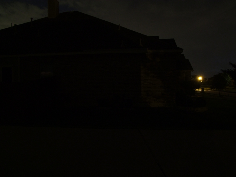
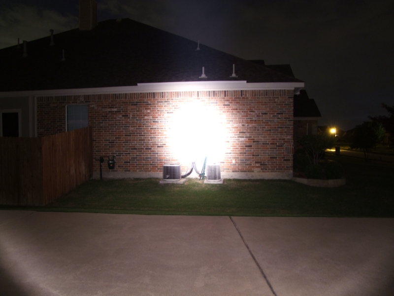
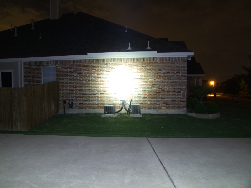
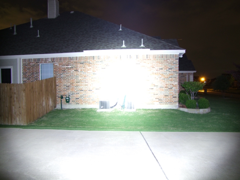
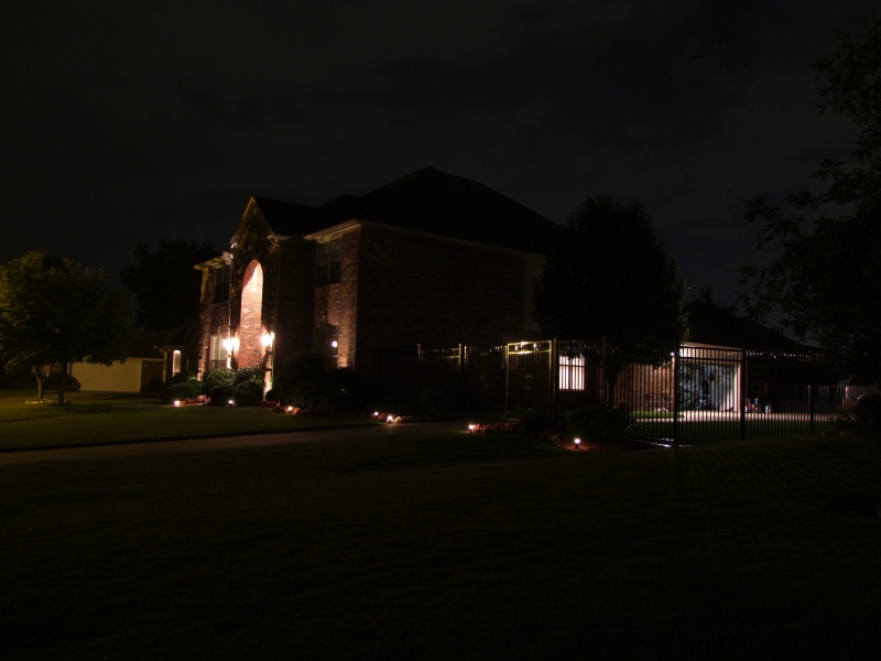
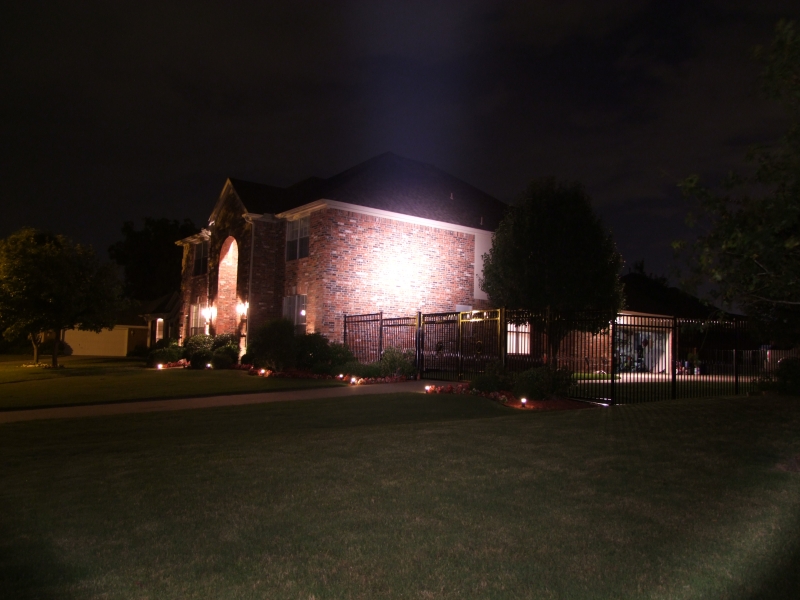
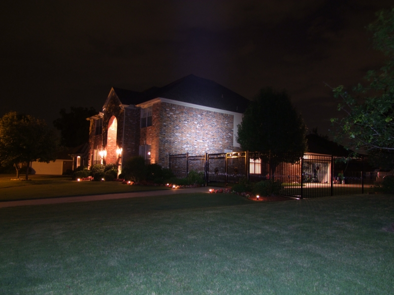
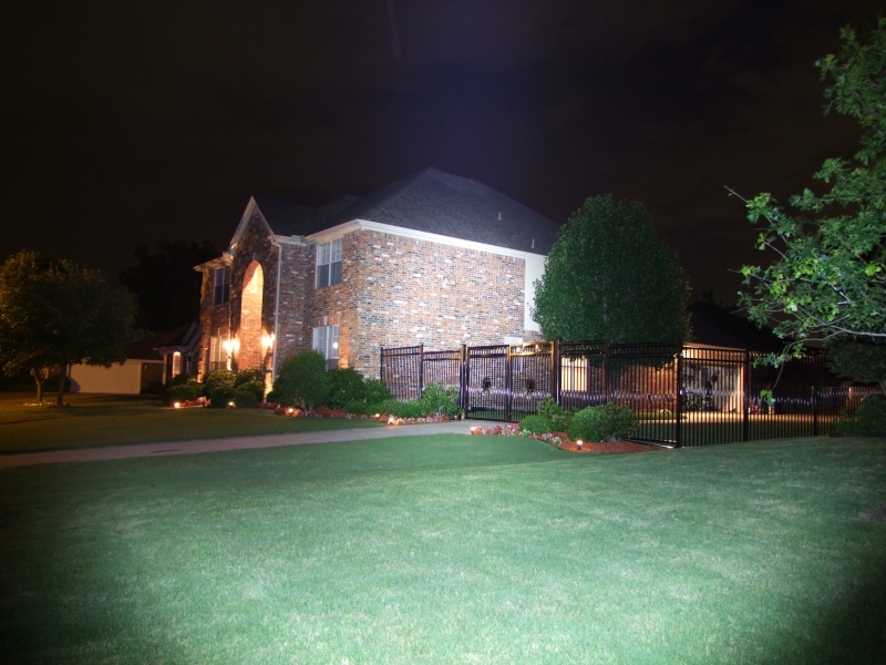
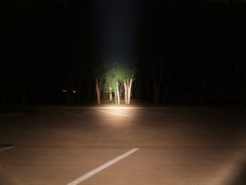
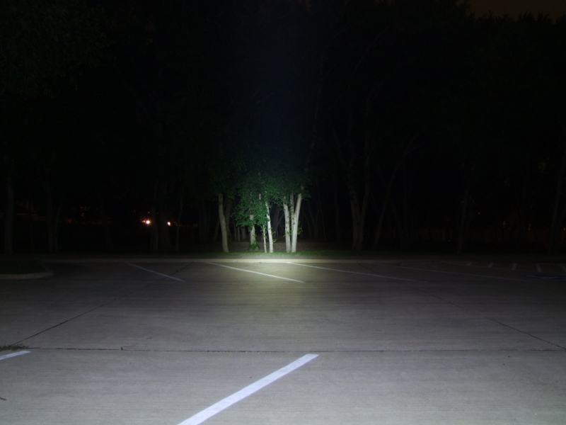
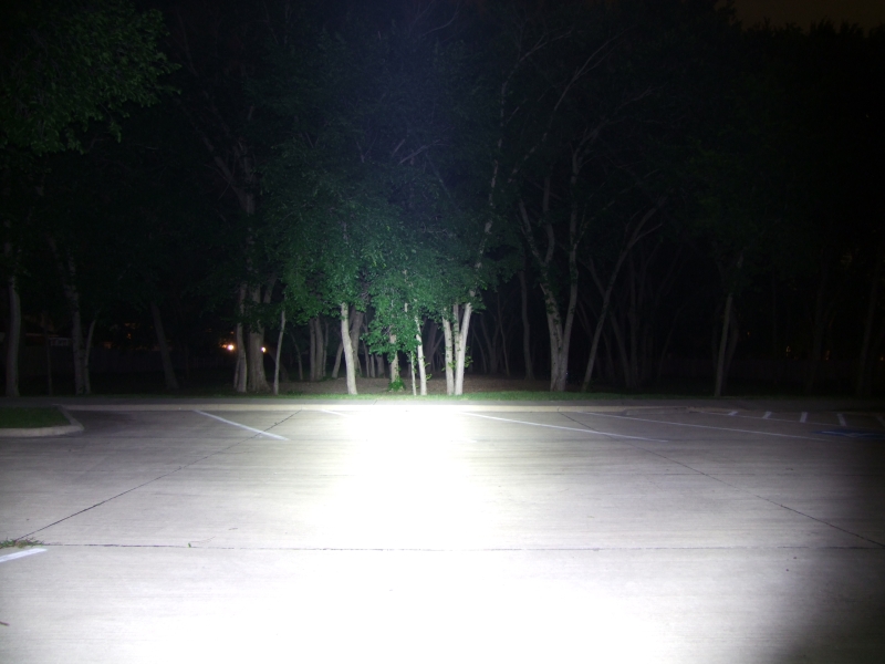
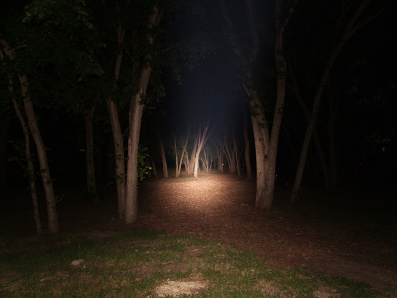
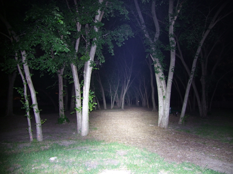
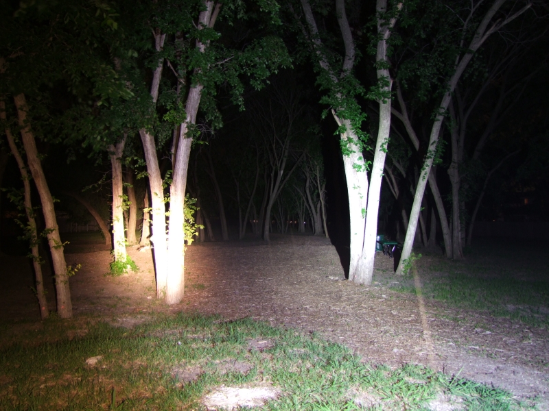
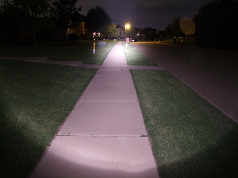
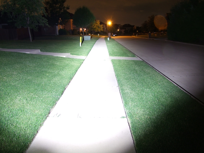


 I believe that more outdoor testing and beamshots are necessary! :laughing: