Mobile Phone Controlled Led Driver - OBSOLETE
See Andriod Controlled Led Driver instead
Note: The Btterm J2ME application used here does not appear to be available any more.
This page is for historical interest only and as an introduction to Andriod Controlled Led Driver using pfodApp which provides many more features then Btterm.
This tutorial extends the Bluetooth Controlled Led Driver
to a Mobile Phone Controlled Led Driver. This tutorial is also at http://www.forward.com.au/MobilePhoneControlledLedDriver/MobilePhoneControlledLedDriver.html
There are three parts to this tutorial,
Connecting your Mobile Phone to Bluetooth Controlled Led Driver
Enhancing the code to provide a more user friendly interface. (Posted)
Outline of the Tutorial
Introduction - Why add Mobile Phone Control
Choosing a Java enabled phone
Checking your existing phone
Loading Java Programs to your Phone
Running the BTTEST Java Program on your Phone
Connecting your Mobile Phone to the Bluetooth Controlled Led Driver
Finding the MAC address of your Bluetooth Module
Starting Bttest
Sending Commands to the Led Driver
Exiting the Terminal Program
Introduction - Why add Mobile Phone Control?
Mobile Phone control of your Led Driver offers a number of advantages
1. A suitable mobile phone provides an inexpensive remote control for your Led Lights.
When I had finished the Bluetooth Controlled Led Driver my first thought was building a remote control. That would have involved another uC, Bluetooth module, small box, push-buttons, batteries and ideally a LCD display and programming. Too much work, so I put off doing it. Then Georgi Bakalski contacted me about his Mobile Phone to bluetooth terminal application http://www.microcontroller-bg.com/btterm This inexpensive java module can be used to turn a suitable mobile phone in to a remote control for your Led Drive. This tutorial describes how to do this.
2. A mobile phone can provide a user friendly interface for setting the various modes available in your torch.
Modern flash lights now come with a wide variety of modes and operational settings, that require flow charts and detailed instructions to access and set. (See Programmable Light User Guides and Flowcharts) The instructions are along the lines of (with a little exaggeration) "Press the switch twice, then start whistling Dixie and on the third bar press the switch again for two bars. The flash light will flash twice (or not) then press the switch x times to set the time-out, etc." Using this Mobile Phone controlled Led Driver you can give the users easy access to all the operational modes and settings of the torch via prompts sent from the torch and displayed on the phone
3.The alpha numeric display on the phone allows you to display information about the state of you torch.
As well as allowing easy setting of the torch modes, the phone can also display the current state of the torch, such as the level of battery charge and count down the time before the torch will auto switch off.
4.Using your mobile phone remote you can add additional functionality to the torch.
Simple useful additional functionally, such as turning the torch on from the phone when you have dropped it in the dark, is available using the software presented here, as is using your phone to control the LED room lighting to set the right mood. Other functionally can be provided with some more programming in the Led Driver. For example, a number of flash lights have a setting which will flash SOS in Morse code. Using your mobile phone you can sent whole messages to the torch to flash out in Morse code. Thanks to my work colleague for suggesting this idea. Other extensions are only limited by your imagination.
Choosing a Java enabled Phone
To use the bluetooth terminal application, Btterm, first you need a Mobile Phone that supports the Java JSR-82 Java Bluetooth API. My old phone did not so I purchased an inexpensive Samsung C3110. I used the website http://www.club-java.com/TastePhone/J2ME/MIDP_Benchmark.jsp to check if the phone would support Java JSR-82.
Checking your existing Phone
If you already have a phone, you can downloaded a test program, bttest.zip, from http://www.microcontroller-bg.com/btterm (after you register).
Loading Java Programs to your Phone
Unzipping bttest.zip gives you two files, BTTEST.jad and BTTEST.jar. You need to transfer these two files to your phone. Depending on the phone, there are three ways to do this:- a) USB cable transfer from your PC, b) copy to a Micro SD card (or similar) and plug the memory into your phone, c) Bluetooth file transfer from your PC.
I used Bluetooth file transfer. Turn the phone on and open "My Bluetooth Places" from the "All Programs" list (under my WindowsXP system). The computer automatically found the phone and listed it. If not you can click "Search for devices in range"
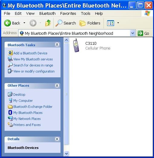
Double clicking on the C3110 icon opens the available connections supported by this phone and the PC's bluetooth stack.
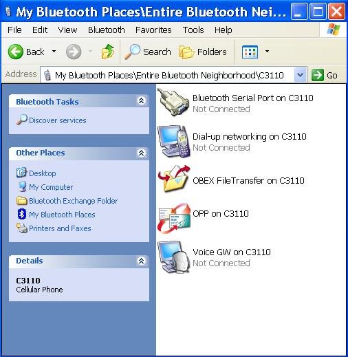
Double clicking on the FileTransfer icon pops up a security dialog in the lower right hand corner of the screen.
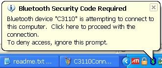
Clicking anywhere in the popup brings up the Security Code Request dialog
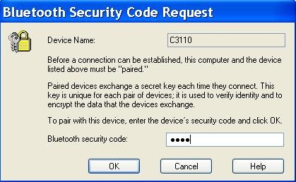
Enter any security code you like, I used 1234, and click OK
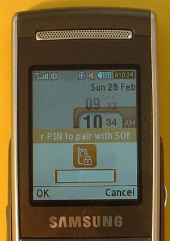
A dialog then pops up on the mobile phone asking for the connection security code. Enter the same code and press OK.
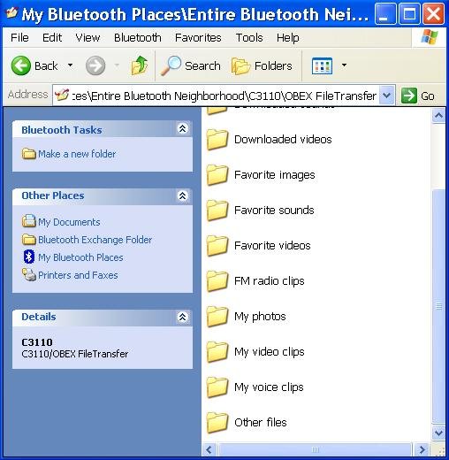
Then a dialog pops up asking if you want to Exchange Data with the PC. Clicking yes sends a folder list to the PC.
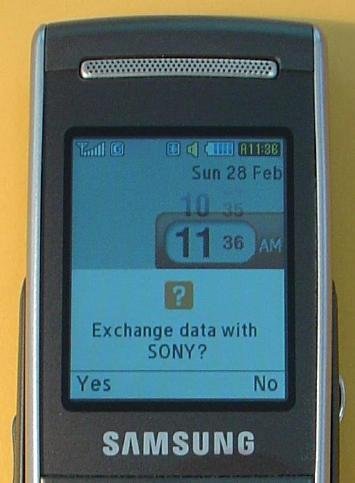
Then drag and drop (or copy and past) the BTTEST.jad and BTTEST.jar files into the "Other files" folder, or some suitable folder on your phone. Again the C3110 prompted me to allow Exchange of Data.
Running the BTTEST Java Programs on your Phone
Now that the files are in your phone you need to Install and run the BTTEST.jad file to see if Java JSR-82 Java Bluetooth API is supported by your phone. If your phone does not even have Java support then you will not be able to run the file at all. To Install and run the BTTEST.jad file, navigate to the folder you saved the files to and select the .jad file (not the .jar file) and your options button should give you the option of installing this program. After which you will be prompted to start it. (Note: If Installation is not one of your options, check you have the .jad file selected.)
My phone automatically prompted me to install the BTTEST application and start it. The application ran and reported detecting Bluetooth API V1.1. Which is the answer you are looking for.
If in doubt send the results displayed to http://www.microcontroller-bg.com/contact-us and ask their advice.
Connecting your Mobile Phone to the Bluetooth Controlled Led Driver
Finding the MAC address of your Bluetooth Module
Having confirmed that your phone supports Java JSR-82 Java Bluetooth API, you can order the BTTERM program from http://www.microcontroller-bg.com/btterm . Each purchase is coded to a given Bluetooth module, so after purchasing you need to supply the MAC address of the bluetooth module you want you phone to connect to.
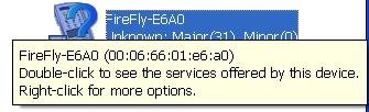
To find the MAC address of your bluetooth module, connect (pair) your bluetooth module to the computer and then right click on its icon and select "Properties" to display the MAC address, or just move the the mouse over the icon. In my case the MAC address for my SparkFun BlueSMiRF_Gold module was 00:06:66:01:e6:a0
Once you have the MAC address of your bluetooth module you can send it to http://www.microcontroller-bg.com and you will receive your copy of Btterm matched to that bluetooth module.
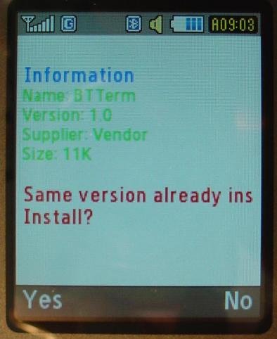
Unzip the Btterm.zip file and transfer both the Btterm.zip and Btterm.jad to your mobile phone, using one of the methods described above. Having transferred the files you need to install and start the terminal program on you phone. The Samsung C3110 prompted me install and start the Btterm program once it had been transferred.
Starting Btterm.
To start it again later you will need to find the .jad file in your phone and click on it and choose the Install or Start option.
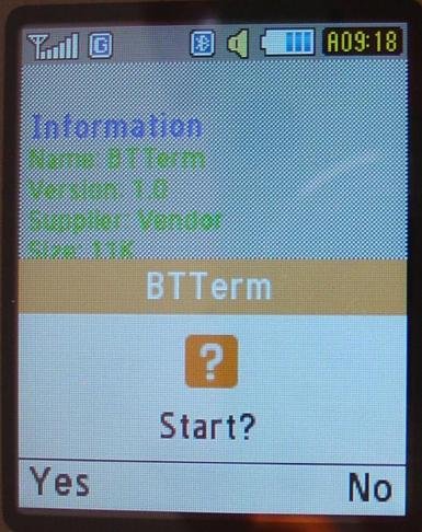
When Btterm started on the Samsung C3110, the phone first prompted me to install it (again).
and then to start it.
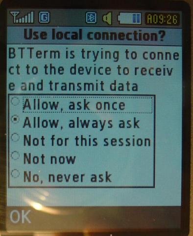
Then the phone prompted me to allow the bluetooth connection.
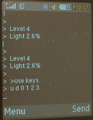
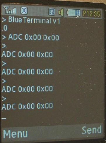
Finally the phone displays the stream of ADC readings sent by the Led Controller.
Sending Commands to the Led Driver
The Btterm program lets you type commands directly into the terminal and then send them using the Send button, but because the Led Driver send another ADC reading every seconds the commands you type in scoll off the display. There are two other ways to send commands. The menu button brings up this menu
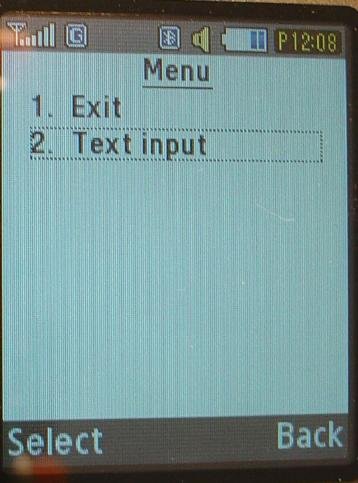
The Text Input option opens a text input screen where you can type the control character you want to send to the led controller, 0, 1, 2, 3, u or d. and then press the Done button to finish editing and then press the OK button send it.
My Btterm program also came with a quick access menu. Pressing the * key opened a menu of Predefined messages and allowed me to select one of the pre-configured commands to send.
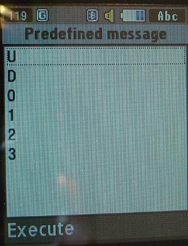
If you want a different set of pre-configured commands, talk to http://www.microcontroller-bg.com about changing the contents of this quick access menu.
Exiting the Terminal Program
As well as using the Exit option from the Menu, pressing the hangup button on the phone prompted me to exit the Btterm program and break the bluetooth connection
Conclusion
This part of the tutorial has shown you how to control your Led Driver from a mobile phone. However the user interface is less then ideal. The third part of this tutorial will cover re-programming the Led Driver to send back user friendly messages and help if the user enters an invalid command. The second part of this tutorial will look at replacing the Bluetooth module with a less expensive one.
See Andriod Controlled Led Driver instead
Note: The Btterm J2ME application used here does not appear to be available any more.
This page is for historical interest only and as an introduction to Andriod Controlled Led Driver using pfodApp which provides many more features then Btterm.
This tutorial extends the Bluetooth Controlled Led Driver
to a Mobile Phone Controlled Led Driver. This tutorial is also at http://www.forward.com.au/MobilePhoneControlledLedDriver/MobilePhoneControlledLedDriver.html
There are three parts to this tutorial,
Connecting your Mobile Phone to Bluetooth Controlled Led Driver
Enhancing the code to provide a more user friendly interface. (Posted)
Outline of the Tutorial
Introduction - Why add Mobile Phone Control
Choosing a Java enabled phone
Checking your existing phone
Loading Java Programs to your Phone
Running the BTTEST Java Program on your Phone
Connecting your Mobile Phone to the Bluetooth Controlled Led Driver
Finding the MAC address of your Bluetooth Module
Starting Bttest
Sending Commands to the Led Driver
Exiting the Terminal Program
Introduction - Why add Mobile Phone Control?
Mobile Phone control of your Led Driver offers a number of advantages
1. A suitable mobile phone provides an inexpensive remote control for your Led Lights.
When I had finished the Bluetooth Controlled Led Driver my first thought was building a remote control. That would have involved another uC, Bluetooth module, small box, push-buttons, batteries and ideally a LCD display and programming. Too much work, so I put off doing it. Then Georgi Bakalski contacted me about his Mobile Phone to bluetooth terminal application http://www.microcontroller-bg.com/btterm This inexpensive java module can be used to turn a suitable mobile phone in to a remote control for your Led Drive. This tutorial describes how to do this.
2. A mobile phone can provide a user friendly interface for setting the various modes available in your torch.
Modern flash lights now come with a wide variety of modes and operational settings, that require flow charts and detailed instructions to access and set. (See Programmable Light User Guides and Flowcharts) The instructions are along the lines of (with a little exaggeration) "Press the switch twice, then start whistling Dixie and on the third bar press the switch again for two bars. The flash light will flash twice (or not) then press the switch x times to set the time-out, etc." Using this Mobile Phone controlled Led Driver you can give the users easy access to all the operational modes and settings of the torch via prompts sent from the torch and displayed on the phone
3.The alpha numeric display on the phone allows you to display information about the state of you torch.
As well as allowing easy setting of the torch modes, the phone can also display the current state of the torch, such as the level of battery charge and count down the time before the torch will auto switch off.
4.Using your mobile phone remote you can add additional functionality to the torch.
Simple useful additional functionally, such as turning the torch on from the phone when you have dropped it in the dark, is available using the software presented here, as is using your phone to control the LED room lighting to set the right mood. Other functionally can be provided with some more programming in the Led Driver. For example, a number of flash lights have a setting which will flash SOS in Morse code. Using your mobile phone you can sent whole messages to the torch to flash out in Morse code. Thanks to my work colleague for suggesting this idea. Other extensions are only limited by your imagination.
Choosing a Java enabled Phone
To use the bluetooth terminal application, Btterm, first you need a Mobile Phone that supports the Java JSR-82 Java Bluetooth API. My old phone did not so I purchased an inexpensive Samsung C3110. I used the website http://www.club-java.com/TastePhone/J2ME/MIDP_Benchmark.jsp to check if the phone would support Java JSR-82.
Checking your existing Phone
If you already have a phone, you can downloaded a test program, bttest.zip, from http://www.microcontroller-bg.com/btterm (after you register).
Loading Java Programs to your Phone
Unzipping bttest.zip gives you two files, BTTEST.jad and BTTEST.jar. You need to transfer these two files to your phone. Depending on the phone, there are three ways to do this:- a) USB cable transfer from your PC, b) copy to a Micro SD card (or similar) and plug the memory into your phone, c) Bluetooth file transfer from your PC.
I used Bluetooth file transfer. Turn the phone on and open "My Bluetooth Places" from the "All Programs" list (under my WindowsXP system). The computer automatically found the phone and listed it. If not you can click "Search for devices in range"
Double clicking on the C3110 icon opens the available connections supported by this phone and the PC's bluetooth stack.
Double clicking on the FileTransfer icon pops up a security dialog in the lower right hand corner of the screen.
Clicking anywhere in the popup brings up the Security Code Request dialog
Enter any security code you like, I used 1234, and click OK
A dialog then pops up on the mobile phone asking for the connection security code. Enter the same code and press OK.
Then a dialog pops up asking if you want to Exchange Data with the PC. Clicking yes sends a folder list to the PC.
Then drag and drop (or copy and past) the BTTEST.jad and BTTEST.jar files into the "Other files" folder, or some suitable folder on your phone. Again the C3110 prompted me to allow Exchange of Data.
Running the BTTEST Java Programs on your Phone
Now that the files are in your phone you need to Install and run the BTTEST.jad file to see if Java JSR-82 Java Bluetooth API is supported by your phone. If your phone does not even have Java support then you will not be able to run the file at all. To Install and run the BTTEST.jad file, navigate to the folder you saved the files to and select the .jad file (not the .jar file) and your options button should give you the option of installing this program. After which you will be prompted to start it. (Note: If Installation is not one of your options, check you have the .jad file selected.)
My phone automatically prompted me to install the BTTEST application and start it. The application ran and reported detecting Bluetooth API V1.1. Which is the answer you are looking for.
If in doubt send the results displayed to http://www.microcontroller-bg.com/contact-us and ask their advice.
Connecting your Mobile Phone to the Bluetooth Controlled Led Driver
Finding the MAC address of your Bluetooth Module
Having confirmed that your phone supports Java JSR-82 Java Bluetooth API, you can order the BTTERM program from http://www.microcontroller-bg.com/btterm . Each purchase is coded to a given Bluetooth module, so after purchasing you need to supply the MAC address of the bluetooth module you want you phone to connect to.
To find the MAC address of your bluetooth module, connect (pair) your bluetooth module to the computer and then right click on its icon and select "Properties" to display the MAC address, or just move the the mouse over the icon. In my case the MAC address for my SparkFun BlueSMiRF_Gold module was 00:06:66:01:e6:a0
Once you have the MAC address of your bluetooth module you can send it to http://www.microcontroller-bg.com and you will receive your copy of Btterm matched to that bluetooth module.
Unzip the Btterm.zip file and transfer both the Btterm.zip and Btterm.jad to your mobile phone, using one of the methods described above. Having transferred the files you need to install and start the terminal program on you phone. The Samsung C3110 prompted me install and start the Btterm program once it had been transferred.
Starting Btterm.
To start it again later you will need to find the .jad file in your phone and click on it and choose the Install or Start option.
When Btterm started on the Samsung C3110, the phone first prompted me to install it (again).
and then to start it.
Then the phone prompted me to allow the bluetooth connection.
Finally the phone displays the stream of ADC readings sent by the Led Controller.
Sending Commands to the Led Driver
The Btterm program lets you type commands directly into the terminal and then send them using the Send button, but because the Led Driver send another ADC reading every seconds the commands you type in scoll off the display. There are two other ways to send commands. The menu button brings up this menu
The Text Input option opens a text input screen where you can type the control character you want to send to the led controller, 0, 1, 2, 3, u or d. and then press the Done button to finish editing and then press the OK button send it.
My Btterm program also came with a quick access menu. Pressing the * key opened a menu of Predefined messages and allowed me to select one of the pre-configured commands to send.
If you want a different set of pre-configured commands, talk to http://www.microcontroller-bg.com about changing the contents of this quick access menu.
Exiting the Terminal Program
As well as using the Exit option from the Menu, pressing the hangup button on the phone prompted me to exit the Btterm program and break the bluetooth connection
Conclusion
This part of the tutorial has shown you how to control your Led Driver from a mobile phone. However the user interface is less then ideal. The third part of this tutorial will cover re-programming the Led Driver to send back user friendly messages and help if the user enters an invalid command. The second part of this tutorial will look at replacing the Bluetooth module with a less expensive one.
Last edited:
")