
I finally got myself a Stanley hid spotlight a few days ago, I have always been curious about the startup/boost circuit, this is what I found.
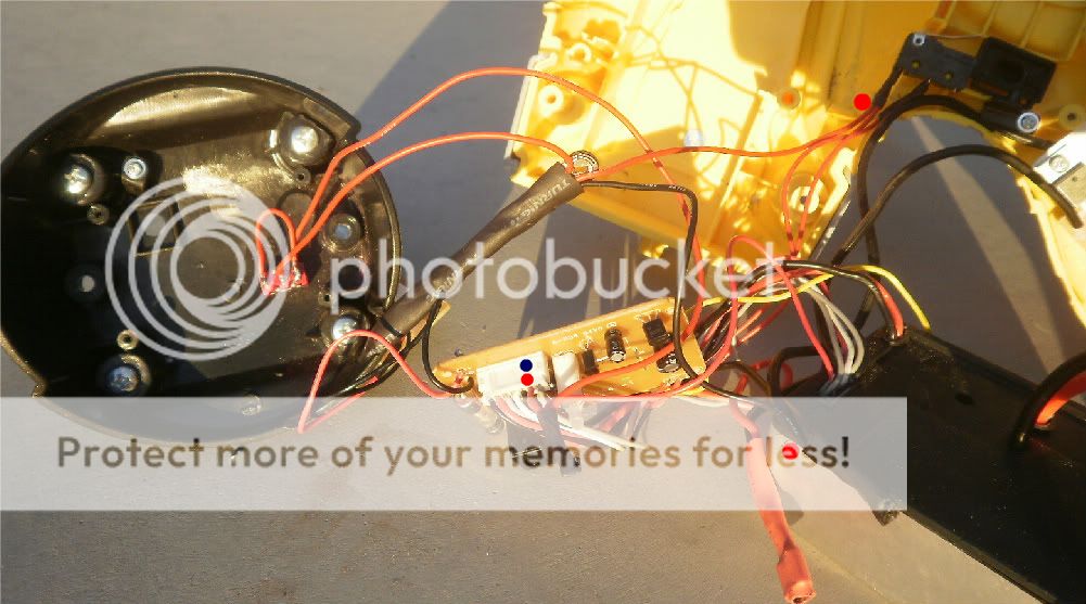
The rear tail stand cover contains a PCB, this controls charging and luckily also the power output from the ballast unit.
The picture below shows the internals of the spotlight, I have placed a red/blue dot on the PCB connector, this is the control signal to the ballast that regulates output power, in normal operation with the standard battery it ranges from .75 to 2 volts, though its own upper limit is 2.7v, and the lower practical limit is whatever voltage corresponds to the ballast operating at 20W, below 20w it will cut out.
All the power reading are taken from the ballast supply lines, I assume the bulb Watts would be close to 85% of the given figures.
Upon startup the Ballast operates at 77 Watts, drifting down to 40 Watts continuous.
Once the bulb is hot, the ballast operates in a constant power mode, in standard form the ballast runs rock solid at 40 Watts input, from 9.6 volts to 15 volts, unfortunately my usual power supply was broken and I could not find the high voltage cut out.
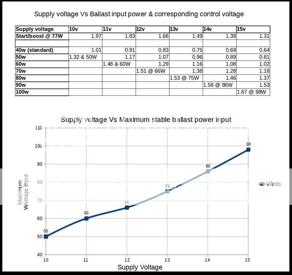
As the supply voltage increases the control voltage decreases to keep the output power constant, you can see this by following the 40 Watts line in the below spreadsheet, from 1.01V to 0.64V.
The rest of the spreadsheet shows the control voltage needed to achieve a power level at a given input voltage.
The ballast operated at as much as 125W on a hot bulb for 5-10 seconds, however at each supply voltage level there was a maximum Wattage that the ballast would settle to, the higher the supply voltage the higher this wattage was, the graph below shows this curve at points from 10 to 15 volts.
The standard SLA battery in my case is only good for 2Ah, it has a 60mOhm IR and on a fresh charge sags to 12.4v under load, when I switch my pot mod on it sags to 12.1v therefore giving around 67 Watts, falling to 50 Watts at 10 Volts.
Due to this I have simply set my pot mod to deliver 1.5 volts to the control circuit when activated, setting the ballast to maximum output with no constant power regulation.
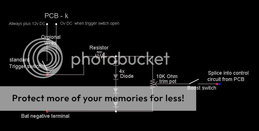
The device I made is as follows, it contains only a few cheap components.
1x, 10K Ohm trim pot.
1x, 600 Ohm resistor.
1x, switch.
4x, Diodes.
The rear tail stand cover contains a PCB, this controls charging and luckily also the power output from the ballast unit.
The picture below shows the internals of the spotlight, I have placed a red/blue dot on the PCB connector, this is the control signal to the ballast that regulates output power, in normal operation with the standard battery it ranges from .75 to 2 volts, though its own upper limit is 2.7v, and the lower practical limit is whatever voltage corresponds to the ballast operating at 20W, below 20w it will cut out.
All the power reading are taken from the ballast supply lines, I assume the bulb Watts would be close to 85% of the given figures.
Upon startup the Ballast operates at 77 Watts, drifting down to 40 Watts continuous.
Once the bulb is hot, the ballast operates in a constant power mode, in standard form the ballast runs rock solid at 40 Watts input, from 9.6 volts to 15 volts, unfortunately my usual power supply was broken and I could not find the high voltage cut out.
As the supply voltage increases the control voltage decreases to keep the output power constant, you can see this by following the 40 Watts line in the below spreadsheet, from 1.01V to 0.64V.
The rest of the spreadsheet shows the control voltage needed to achieve a power level at a given input voltage.
The ballast operated at as much as 125W on a hot bulb for 5-10 seconds, however at each supply voltage level there was a maximum Wattage that the ballast would settle to, the higher the supply voltage the higher this wattage was, the graph below shows this curve at points from 10 to 15 volts.
The standard SLA battery in my case is only good for 2Ah, it has a 60mOhm IR and on a fresh charge sags to 12.4v under load, when I switch my pot mod on it sags to 12.1v therefore giving around 67 Watts, falling to 50 Watts at 10 Volts.
Due to this I have simply set my pot mod to deliver 1.5 volts to the control circuit when activated, setting the ballast to maximum output with no constant power regulation.
The device I made is as follows, it contains only a few cheap components.
1x, 10K Ohm trim pot.
1x, 600 Ohm resistor.
1x, switch.
4x, Diodes.
Last edited:

 :thumbsup:


