
Seen here is my existing MT-G2 Build.

Today it's getting an Upgrade.

XHP70 - N2 Bin in a 5A Tint.
I don't much care for the Cold tints, which is why I was glad it was offered in a slightly warmer 5A.
The 5000k MT-G2 is about as cold as I like. The 4000k version was better but kind of funny.

Seen here is the MT sitting atop an H22a. P7 Flat Top D, I believe. Not quite sure, it was given to me.
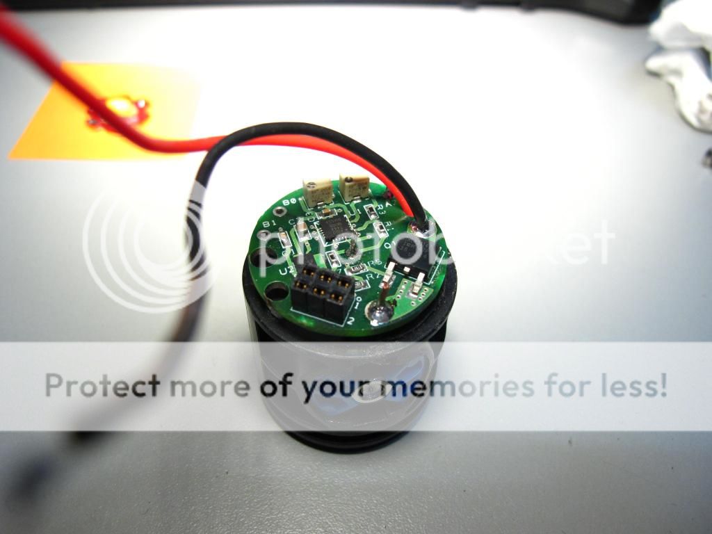
My Driver? A JM-PHD-D1 Programmable PWM FET.
Yes, it's designed for Incan. It's not a proper Buck. It only works with voltages 5.2v or higher and all it is is a PWM, so the voltage of the batteries has to match the load.
As we all know, the MT-G2 runs great off a pair of Li-ions, so this PWM driver has proven to be an excellent option for controlling the MT, and as I've since found, the XHP70.
If you don't already know, you can buy this unit here off the sales section.
If has 2 pots on it. One sets the full power level, the other sets the low voltage cut off.
It has an interface port, which if the have the correct adapter and software, lets you program this this via USB to set it extra functions, like overheat temp cutoff (read turbo timer) and it's levels.
Instructions to build the Driver module are here:
http://www.candlepowerforums.com/vb...imag-Updated-JM-PH-D1-Build&highlight=ultimag
Just sub the socket for LED wire leads, and don't mod the switch for momentary.
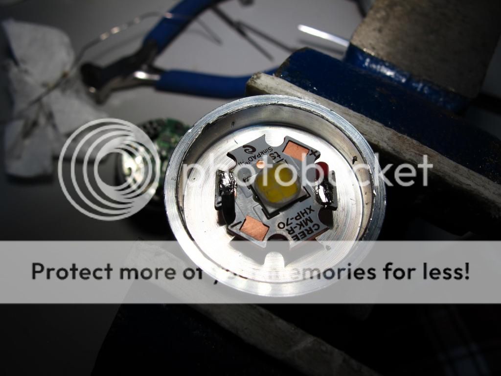
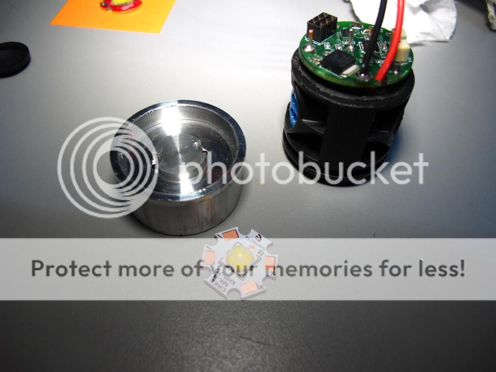
To 20mm XHP sits nicely on the H22. Use some sink goo of course. I also put some around the sink body which is a nice tight fit in my particular mag body.
Once together, I grabbed a couple of 26650 IMR cells and started calibration.
The power level pot, labeled as Vbulb in the instructions, was simply dialed in to give me 5.35amp at the tail cap.
That's the great thing about this driver, Just dial in whatever Current you want. You can set it mild, or you can crank it to direct drive.
Bare in mind that the mode levels are a % that is directly proportional to the max out setting dialed in.
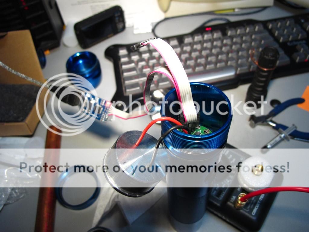
Seen here, I have the driver plugged into the computer for further calibration.
I set it up with it's maximum available 4 mode settings.
1st: 40% which gave me 750mah at the tail, which gives me the perfect balance of output and runtime for a good user light.
This driver has no memory so it will always start at 40% going straight to my typical operation level.
2nd: 18%, this is the lowest level available in the programming. About 150mah as the tail.
3rd: 71%, this gives me about 2.5a at the tail for bright output with less heat and more runtime.
4th: is 100% by default, 5.35 amps cranking the XHP to all it's glory with just a touch of overdrive over it's rated 4.8a.
IF you were to order a JM switch and cannot program it, I recommend requesting these modes.
I have actually found in practice, since I calibrated it using my best high output batteries (Panasonic 26650 hybrid 2650mah), 100% will settle at 4.8a with other more average IMR cell. (MNKE IMR 26650 3500mah)
I'm sure I can dial up the MNKE's to 5.35a but that heatsink is a pain to get out.
In other news, with the MT-G2 I has the temp cut off set to 50c. This might seem like not lots, but the sensor is on the MCU. Which means by the time whatever the temp is at the MCU is much higher at the LED.
If I recall correctly, I got at least 10mins, or was it 20? of sustained full power output with the MT @ 3.3a at this setting.
I've ramped it up to 70c for the XHP, knowing that it can handle high temps hoping to extend the full output runtime.
Maybe one of these days I'll time it. I'm not very scientific am I ?

The JM actually has a secret 5th mode when running LEDs.
It's all in the switch. Normally, when you build a JM Mag, use mod the switch to be momentary.
I did not. I blip the switch momentary to control the driver, but if I click the switch on and leave it, the JM MCU running in standby, leaks some current to the LED giving you a 5th moonlight mode. So remember, if you build this, don't mod the switch so you can have moonlight mode.
It works out really well, cause if you click the mag on from off, it goes straight to moonlight. If wait 2 seconds before clicking it off, it turns off. No accidental activation of higher modes, no having to cycle thru said modes to get moonlight.
A special note on the modes . . .
This is a PWM FET designed for Incan, as such, the PWM speed is slower than normal LED drivers.
So this means there is a slight bit of flicker. It's only really noticeable in the lowest mode, and only really if you move the light around quickly and/or are looking for it.
It's barely noticeable if at all, in the mid modes, and at high, forget about it, you can't tell even if you wanted to.
I cant' anyway. I have sensitive enough eyes and it doesn't bother me.
I've already discussed this project with Jimmy, and talked about ramping up the PWM speed. He said it can be done.
Maybe if there is enough interest in this driver for running LED's he'll do it up.

The reflector I'm using is a DX #13803. It comes with a crappy pill/slug/whatever which I did not use, but it fits damn near perfect with my H22a.
I did have to lathe the edge of the reflector to fit the mag head however, making this particular build not as easy peasy.
However, if you have a reflector that fits, you can easily and awesomely run and MT-G2 or XHP70 using this underrated PWM FET driver.
Today it's getting an Upgrade.
XHP70 - N2 Bin in a 5A Tint.
I don't much care for the Cold tints, which is why I was glad it was offered in a slightly warmer 5A.
The 5000k MT-G2 is about as cold as I like. The 4000k version was better but kind of funny.
Seen here is the MT sitting atop an H22a. P7 Flat Top D, I believe. Not quite sure, it was given to me.
My Driver? A JM-PHD-D1 Programmable PWM FET.
Yes, it's designed for Incan. It's not a proper Buck. It only works with voltages 5.2v or higher and all it is is a PWM, so the voltage of the batteries has to match the load.
As we all know, the MT-G2 runs great off a pair of Li-ions, so this PWM driver has proven to be an excellent option for controlling the MT, and as I've since found, the XHP70.
If you don't already know, you can buy this unit here off the sales section.
If has 2 pots on it. One sets the full power level, the other sets the low voltage cut off.
It has an interface port, which if the have the correct adapter and software, lets you program this this via USB to set it extra functions, like overheat temp cutoff (read turbo timer) and it's levels.
Instructions to build the Driver module are here:
http://www.candlepowerforums.com/vb...imag-Updated-JM-PH-D1-Build&highlight=ultimag
Just sub the socket for LED wire leads, and don't mod the switch for momentary.
To 20mm XHP sits nicely on the H22. Use some sink goo of course. I also put some around the sink body which is a nice tight fit in my particular mag body.
Once together, I grabbed a couple of 26650 IMR cells and started calibration.
The power level pot, labeled as Vbulb in the instructions, was simply dialed in to give me 5.35amp at the tail cap.
That's the great thing about this driver, Just dial in whatever Current you want. You can set it mild, or you can crank it to direct drive.
Bare in mind that the mode levels are a % that is directly proportional to the max out setting dialed in.
Seen here, I have the driver plugged into the computer for further calibration.
I set it up with it's maximum available 4 mode settings.
1st: 40% which gave me 750mah at the tail, which gives me the perfect balance of output and runtime for a good user light.
This driver has no memory so it will always start at 40% going straight to my typical operation level.
2nd: 18%, this is the lowest level available in the programming. About 150mah as the tail.
3rd: 71%, this gives me about 2.5a at the tail for bright output with less heat and more runtime.
4th: is 100% by default, 5.35 amps cranking the XHP to all it's glory with just a touch of overdrive over it's rated 4.8a.
IF you were to order a JM switch and cannot program it, I recommend requesting these modes.
I have actually found in practice, since I calibrated it using my best high output batteries (Panasonic 26650 hybrid 2650mah), 100% will settle at 4.8a with other more average IMR cell. (MNKE IMR 26650 3500mah)
I'm sure I can dial up the MNKE's to 5.35a but that heatsink is a pain to get out.
In other news, with the MT-G2 I has the temp cut off set to 50c. This might seem like not lots, but the sensor is on the MCU. Which means by the time whatever the temp is at the MCU is much higher at the LED.
If I recall correctly, I got at least 10mins, or was it 20? of sustained full power output with the MT @ 3.3a at this setting.
I've ramped it up to 70c for the XHP, knowing that it can handle high temps hoping to extend the full output runtime.
Maybe one of these days I'll time it. I'm not very scientific am I ?
The JM actually has a secret 5th mode when running LEDs.
It's all in the switch. Normally, when you build a JM Mag, use mod the switch to be momentary.
I did not. I blip the switch momentary to control the driver, but if I click the switch on and leave it, the JM MCU running in standby, leaks some current to the LED giving you a 5th moonlight mode. So remember, if you build this, don't mod the switch so you can have moonlight mode.
It works out really well, cause if you click the mag on from off, it goes straight to moonlight. If wait 2 seconds before clicking it off, it turns off. No accidental activation of higher modes, no having to cycle thru said modes to get moonlight.
A special note on the modes . . .
This is a PWM FET designed for Incan, as such, the PWM speed is slower than normal LED drivers.
So this means there is a slight bit of flicker. It's only really noticeable in the lowest mode, and only really if you move the light around quickly and/or are looking for it.
It's barely noticeable if at all, in the mid modes, and at high, forget about it, you can't tell even if you wanted to.
I cant' anyway. I have sensitive enough eyes and it doesn't bother me.
I've already discussed this project with Jimmy, and talked about ramping up the PWM speed. He said it can be done.
Maybe if there is enough interest in this driver for running LED's he'll do it up.
The reflector I'm using is a DX #13803. It comes with a crappy pill/slug/whatever which I did not use, but it fits damn near perfect with my H22a.
I did have to lathe the edge of the reflector to fit the mag head however, making this particular build not as easy peasy.
However, if you have a reflector that fits, you can easily and awesomely run and MT-G2 or XHP70 using this underrated PWM FET driver.
Last edited: