These are such awesome responses! :thumbsup:
I thought about using a Shark and 4 XR-Es, but the complexity (and cost! :sweat: ) started to snowball. Plus, I'm just not comfortable with wiring LEDs in series (
example - I was probably missing something there, or several things).
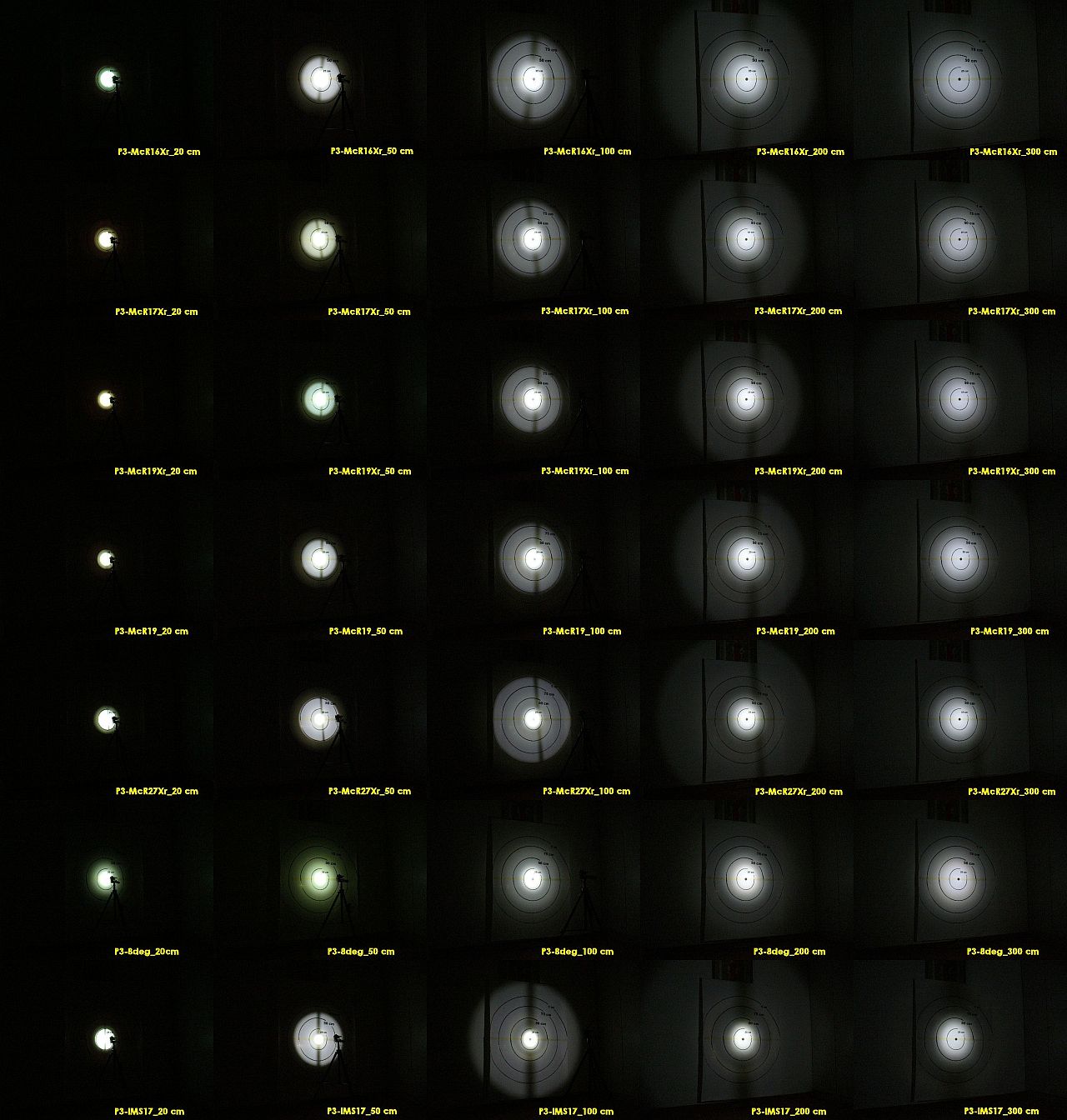
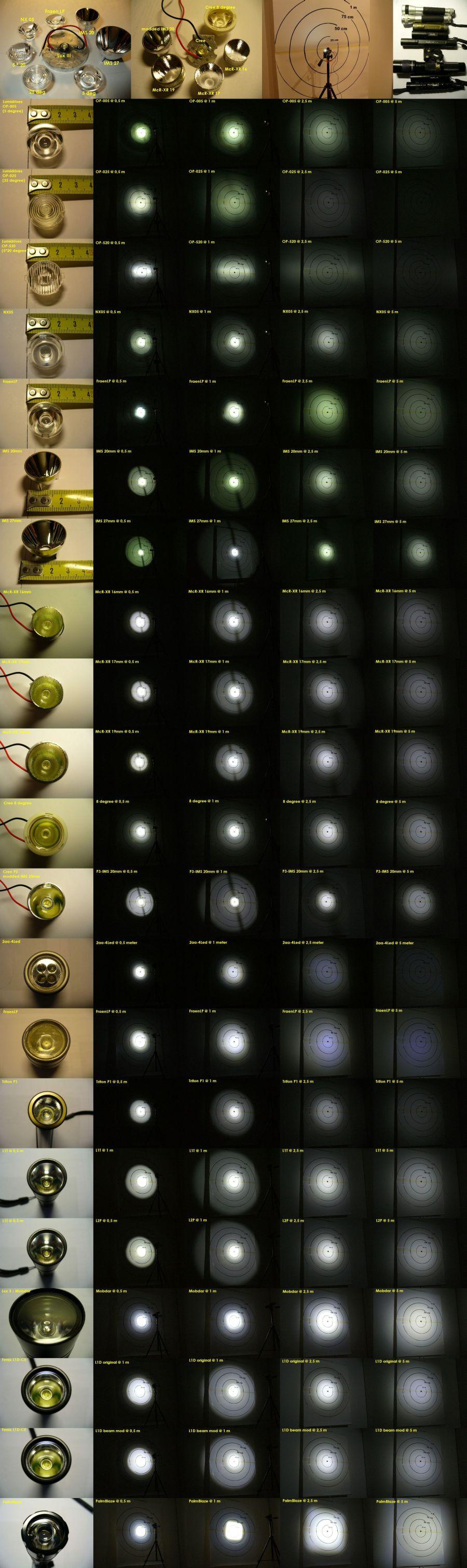
I think I'll go with a Downboy and a single XR-E. It sounds like the McR17XR would be a decent reflector for a wide spot. As for the IMS reflectors, I really don't care if there'd be rings, just as long as there was a smooth hotspot wide enough to light up an entire bike lane or sidewalk.
So, how does a Cree/MCPCB fit under a reflector for proper focus?
How do you mix and use AA epoxy?
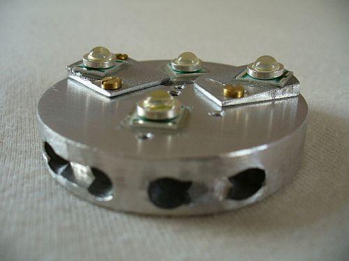
My "plan" right now is to have a 12V SLA powering a Downboy1500 (.05 and .10 ohm sense resistors installed by the Shoppe) powering a P3/P4 XR-E on an MCPCB, focused by a McR17XR (or whatever reflector would give my desired hotspot profile for less money), with the emitter and converter AAed to Zalman fanless aluminum Northbridge CPU heatsinks. I thought I could make a crude body by using aluminum tubing (0.745" ID, 0.875" OD) and popping it on the emitter heatsink, surrounding the reflector. A 22.5mm mineral glass window could then be epoxied to the tubing, environmentally sealing the LE. If necessary, I could make a similar "body" to protect the Downboy.
Now my only problem is mounting these components to a bicycle. I checked out some of the links in the bike light master thread (thanks, Andy!), but the mounts are mostly for standard tubular lights. Ideally, I'd like something that can hold the setup securely, allows aiming, doesn't require permanent alterations, and can be easily detached and reattached for storage or when locking the bike to a post.

")
 ).
). , magic smoke, and there goes a $70 project. Now I know why I prefer hotwires: they're cheaper and bigger.