Little help with ZXLD381 boost driver

tylernt

Enlightened
Joined
Nov 25, 2009
Messages
268
So, I'm about to order up some ZXLD381 chips (https://www.candlepowerforums.com/threads/226903) for experimentation using some Cree 5mm LEDs and I have a few questions before I waste money getting the wrong peripherals for it:

1. Will these inductors work ok?
Axial lead: http://search.digikey.com/scripts/DkSearch/dksus.dll?Detail&itemSeq=91034799&uq=634207804606082154
SMD: http://search.digikey.com/scripts/DkSearch/dksus.dll?Detail&itemSeq=90992063&uq=634207804606082154

2. I want to smooth the current peaks to avoid exceeding 100mA to the LED. The datasheet shows a low-ripple example circuit but it seems to spec an insanely large 1 farad capacitor which would be bigger than the battery powering the flashlight (I hope that's a typo in the datasheet?!). Anyway, I don't care about ripple, I just want to clip the current peak a bit. Without smoothing, the ZXLD381+10uH peaks at 190mA, so I need to cut that about in half... how much of a capacitor do I need? Is there at least a formula to calculate that (not asking you to do my homework for me ;) ).
 

Selectron

Newly Enlightened
Joined
Jul 21, 2010
Messages
25
Location
UK
Are you still going ahead with this one or have you moved on to a 'plan B'? Or did you just go ahead and order the components anyway? The links to the inductors don't work, if you want to try re-posting them, or maybe quote the manufacturer and part numbers and we can find them that way.

There is a formula which I believe should apply when calculating the capacitor value. The ZXLD381 datasheet only shows detailed current and voltage waveforms for a 4.7uH inductor, but when I apply the formula to that I arrive at a value of 0.76uF, which would tie in nicely with the stated value if that's just a typo, intended to be 1uF instead the outrageously colossal 1F. I won't launch into an explanation in case you've moved on to plan B, but if you're still intending to use that chip and components then let me know and I'll explain how I arrived at 0.76uF, for which, in practice, I would use a 1uF component.
 

tylernt

Enlightened
Joined
Nov 25, 2009
Messages
268
I went ahead and ordered the stuff, so we'll soon see if it works. For the cap, I ordered a few 47uF to use in parallel so even one may be a bit of overkill :eek:. But I suppose I can always go to Rat Shack for a 1uF.

I am very curious to see your equation. Is it the same equation used to smooth rectified A/C ripple?

The inductors were Digikey part numbers DN42077-ND and 587-2053-1-ND. My main concern is the 587-2053-1-ND because it's a teeny tiny SMD part... I know 22uH is 22uH, but most mass-produced LED drivers I've seen (from DX etc) use a physically larger coil (MUCH larger) so I wasn't sure if the little guy would do the job.
 

Selectron

Newly Enlightened
Joined
Jul 21, 2010
Messages
25
Location
UK
It is indeed a formula to calculate the capacitance required to reduce ripple following rectification, so it would often be used at much lower frequencies - 50Hz for half-wave here in the UK, or 100Hz for the more common full-wave (60Hz/120Hz in the USA). The datasheet states the nominal frequency of your IC as 350kHz, which is good news because the value of capacitance required for smoothing falls as frequency increases, and your load current is low, so again that's good news because the lower the current, the lower the value of capacitance required.

So, the formula is C = I x dt / dV

... where C is the capacitance in farads, I is the load current in amps, dt is the time duration in seconds for which the capacitor alone will be powering the load, and dV is the maximum amplitude of ripple for which we're aiming, in volts.

We shouldn't need to do the calculation of course, because the tables on the datasheet tell us that when using a 10uH coil, the current will be 190mA peak, 30mA average, if unsmoothed, or 27mA (continuous) if smoothed - but of course there's that ambiguity about the value of capacitance used, so we're only doing the calculation to get an approximate value for C.

You'll be using 10uH, for which we don't have detailed data, but there are excellent current and voltage waveforms shown for 4.7uH so we'll use that for the calculation.

Returning to the formula, the datasheet table tells us that current is 50mA when smoothed, so our value for 'I' is already known.

For dt, we first need to know the time duration for one full cycle, then subtract the duration for which the capacitor is receiving a charging current - the remainder is 'dt' - the time during which the capacitor alone powers the load. I think it would count as 'fair usage' if I borrow one diagram from the datasheet to illustrate a point, so the current and voltage waveform diagram is shown below. Points A & B mark the start and end of one full cycle, which occupies 5.5 horizontal divisions at 500ns/div = 2.75us (incidentally, since f = 1/t, we also know that the frequency at that instant was 363.6kHz).

So we have the time period for one cycle, and now we subtract the time during which the capacitor will be receiving charging current. The current rises very rapidly to a peak of 340mA (3.4 vertical divisions at 100mA/div), falling more slowly, in a linear manner. From the datasheet, the current when smoothed is 50mA, so I'll take the point at which the current falls to 50mA as being the point at which the capacitor effectively takes over and starts to power the load - I've marked that as point C, and it occurs 1.4 horizontal divisions after the current first started to rise, so that's 1.4 x 500ns/div = 0.7us. If we now subtract that from our time period for one cycle then that will give us dt, so 2.75us - 0.7us = 2.05us.

ledwaveforms01.gif


Finally we need our ripple voltage, for which I'll use the high and low points of the plateau, atop the voltage waveform. When the current initially peaks, the voltage amplitude also peaks at about 3.58 vertical divisions at 1V/div = 3.58V (point D). The lower corner of the plateau at the point just before the LED's Vf falls rapidly is about 3.44V (point E), so if we subtract that from the peak voltage, we will have a figure for the ripple voltage, so Vripple = 3.58V - 3.44V = 0.14V.

The reason why I've chosen that point as our lowest target voltage is because if we allow the voltage to fall much lower, then the drive waveform will begin to resemble a square wave, and when mentioning that capacitor, the datasheet states quite clearly, 'low ripple', so I think that's about the lowest we can allow the voltage to fall and still justifiably describe it as being steady DC with a low ripple component.

So now we can put the numbers into the formula:

C = I x dt / dV

C = 50 x 10^-3 x 2.05 x 10^-6 / 0.14

C = 0.1025 x 10^-6 / 0.14

C = 0.73 x 10^-6

C = 0.73uF

And that's how I arrived at that value (I was using slightly different timings when I arrived at 0.76uF), and that's close enough to 1uF that I would feel confident in assuming a typo in the datasheet, intended to read as 1uF. I didn't look at the inductors yet but I'll take a look at them tomorrow.
 
Last edited:

tylernt

Enlightened
Joined
Nov 25, 2009
Messages
268
Wow Selectron thank you VERY much for the detailed explanation. I was able to follow your math and get the same answer :) so that's good. Plugging in the numbers for the 10uF/27mA application , I get .40uF so a common .47uF cap should work, I would think.

However, this is assuming that the frequency stays the same with different values of inductor, which I imagine it probably does not (and I don't have an oscilloscope to find out what frequency it will run at). Still, .47uF should get us in the ballpark, especially since we don't need to totally eliminate "ripple" -- just shave the peaks to avoid zapping the LED with more than 100mA at any given point in the cycle.
 

Selectron

Newly Enlightened
Joined
Jul 21, 2010
Messages
25
Location
UK
I think the timings must vary considerably depending on inductor value, so you can't really take the timings from the 4.7uH circuit and slot them into the equation for a different value of inductor, and you've demonstrated that by putting the 4.7uH timings into the 10uH circuit and obtaining a different value for C, when the datasheet table indicates that the same value of capacitor applied in all cases - therefore the timings must be the variable, although there might also be a slight variation in ripple voltage which they haven't mentioned.

The operating frequency is determined by the IC's internal oscillator and control circuit, and the current is determined by the value of inductance, with dt being determined by those two factors in combination. So changing the value of C will only alter the ripple voltage, dV.

A better approach would therefore be to make dV the subject of the formula, and then do the calculation for the 4.7uH circuit using different values of C, and assume a similar effect when using other values of inductor with that value of C.

Ripple voltage is inversely proportional to the value of C, so if you double C then the ripple will halve, or if you halve C then the ripple will double. To find the ripple voltage for any given value of C though, use I = 50mA, dt = 2.05us, use your own choice of value for C and then transpose the formula:

C = I x dt / dV

therefore:

dV = I x dt / C

On the inductors, I think the physically larger 10uH will work fine. I was doubtful about the SMD coil, but the datasheet seems to indicate that it's a low DC resistance type, and it is intended for low power DC to DC converters, so there's a good chance that will also do the job, because at 22uH the peak current would only be 80mA, average 15mA, or a smoothed 13.5mA, and that's all comfortably within its 175mA current rating. It is a tiny package though so if using it then check that it doesn't heat up too much when the circuit is operating.
 

tylernt

Enlightened
Joined
Nov 25, 2009
Messages
268
Hm. If the frequency decreases as inductor size increases, then dt probably also gets longer, which would require a proportionally larger smoothing cap... except I is also proportionally smaller, so maybe the effects cancel out and 1nF is about right for most circumstances? Maybe I should just ask Zetex. :D

Anyway, all my stuff arrived today. Man, I knew SMT parts were small, but... not THIS small! Soldering this up is going to be a challenge for sure. I just now learned about solder paste, I probably should have ordered some the same time I got these parts, sigh. Any good way to solder SMD without paste?
 

Selectron

Newly Enlightened
Joined
Jul 21, 2010
Messages
25
Location
UK
For the capacitor, I'd say any value between 0.47uF and 10uF would be fine. This is the calculation for ripple voltage (dV) using 0.47uF:

dV = I x dt / C

= 50 x 10^-3 x 2.05 x 10^-6 / 0.47x 10^-6

= 0.1025 x 10^-6 / 0.47x 10^-6

= 0.218

dV = 0.218V (218mV or 218 x 10^-3 V)

If you want to, you could even use the 47uF which you ordered. Normally it's a real bad idea to use an excessively large smoothing capacitor because if it's fed from a low impedance source then the inrush current can cause damage to the preceding circuitry - especially the diodes in a rectifier application, so sometimes a limiting resistor is added prior to the capacitor to limit that current. It doesn't really apply in your case though because you simply don't have much current available, and if you're using the specified diode then it's a high current device so it won't come to any harm. It would probably take a few cycles to charge a 47uF so there might be just a fractional delay after switching on before the LED comes up to full brightness, but it will likely charge so quickly that you won't even notice it. Only 2mV of ripple at 47uF by the way so you'd feeding it with almost-clean, continuous DC.

I was looking at my smallest driver board, and the coil on that is only tiny - larger than your SMD but still pretty small at 3mm x 3.2mm x 2mm depth, open construction on a ferrite core:

drivercoil.jpg


That's from a single-cell torch which draws 70mA from a AAA NiMH, so that's probably somewhat less than 20mA to the LED - you can see how tiny the inductor is beside the 5mm LED.

Even normal soldering would a pretty difficult thing to describe, so you'd probably be better off looking at some videos - if you search for SMD soldering on youtube you'll find a stack of tutorial vids on there. Some of them will be using separate flux but if you are using resin-cored solder instead you would still follow the same technique, but just skip the part where the flux is applied. Some fine tweezers can be handy but they aren't essential, but a fine tip on the soldering iron is a real big help.
 

datiLED

Flashlight Enthusiast
Joined
May 9, 2006
Messages
2,023
Location
Atlanta, GA
I have been building these circuits for a while now, and find them to be good performers. I am using a 22uH (13.5mA) or 15uH (18mA) inductor, and a 1uF capacitor. Your choice of a 47uF should be more than sufficient. For the diode, I am using a BAT-54. It was a good compromise of performance and price. I am using a small Murata inductor, though I don't have the part number handy.

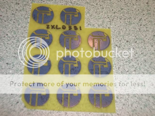
Here are a few pictures of the board that I designed and built. I prefer to build using a PCB, though I have done a lot of these type circuits dead bug style.

100_0807.jpg


100_0808.jpg


100_0810.jpg


To solder the components, I tack on one end of each component, and then solder the remaining connections. I find that solder and a little flux makes for easier soldering. I have used solder paste in the past, but it didn't work as well for me as the thin solder that I am using. I may try it again in the future though.

Good luck with your build. Post a few pictures when you get done.
 

tylernt

Enlightened
Joined
Nov 25, 2009
Messages
268
Cool, I ended up with a BAT-48 diode which looks to be slightly beefier (and in a through-hole package).

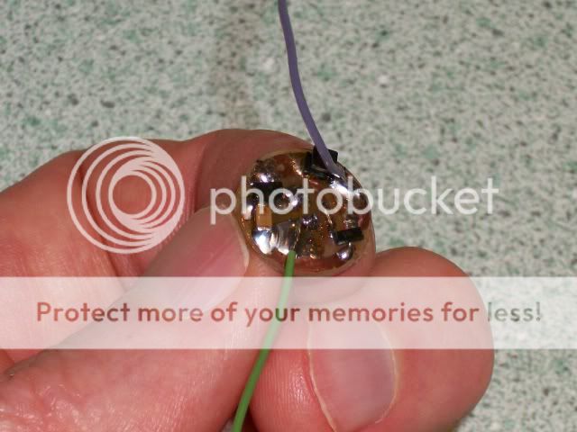
I'm actually using the ZXLD381 for two projects -- one is with the 22uH SMT soldered directly to 5mm LED legs. I read up on SMT soldering techniques more, and I think I'm going to flux the ZXLD381 and then hold it on the legs of a 5mm LED with tweezers, then apply my well-tinned iron and hope the flux draws the solder into the joint. Once I have the ground pin soldered so the chip will hold itself on, I can hold the inductor across the 2 pins on the other side of the SOT23 with tweezers and solder it to the other LED leg. I'm hoping this will give me something similar to Illum's setup at the end of the other thread linked to above.

For my other project I think I'm going to put solder on the copper pads some perfboard, then press the fluxed SOT23 legs into the solder with my fine iron tip, remelting the solder and "sinking" the legs into it. I can then bridge the copper pads to adjacent holes to make connections to the other components. This is where I'll use the smoothing cap + diode.
 

tylernt

Enlightened
Joined
Nov 25, 2009
Messages
268
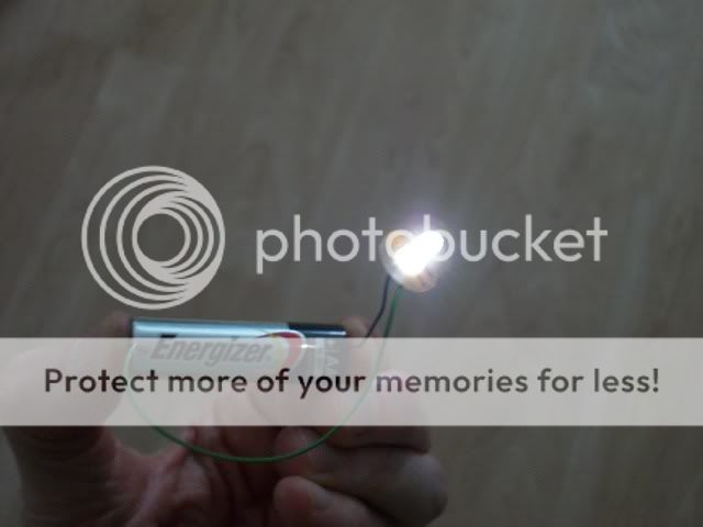
It works!! :wow:

The technique I proposed worked perfectly for the between-the-legs circuit. I got some rosin flux from Rat Shack that's a little sticky and helps hold components in place so they don't fall on the carpet and disappear forever. Work as follows: clamp the LED head in Helping Hands using paper to protect the epoxy from the jaws. Flux all ZXLD381 pins and lay it between the legs, face down. Touch tinned soldering iron to ZXLD381 ground pin resting on the LED - leg. Then, carefully, clip the + LED leg between the ZXLD381 input and output with wire cutters. Flux inductor and stick it to the LED + leg and ZXLD381 output, then touch with tinned soldering iron. The last part is a little tricky, you need to hold the cut and fluxed leg back up to the ZXLD381 input pin and to the other side of the inductor, then apply tinned iron as before.

Many thanks for your help, Selectron and datiLED! :thumbsup:

Enjoy the pics that follow... I'll tackle the perfboard project another time.

2gy9hmg.jpg

rtgobs.jpg


Grabbed a LR44 (1.5v alkaline) button cell to test.

4u9953.jpg


Draws about 30mA from the three batteries I tried, the LR44, an AAAA, and an AAA, all alkaline. Since the LED should be averaging 15mA, this doesn't seem terribly efficient, but then again I am using an inductor that is probably not ideal. And my cheap DMM probably contributes a bit of resistance. Still, it works! :D
 

Selectron

Newly Enlightened
Joined
Jul 21, 2010
Messages
25
Location
UK
We have light - well done! :goodjob: That sure is a compact circuit, eh.

If you draw 30mA from the alkaline cell and only get 15mA at the LED, that might sound like a raw deal, but remember that you're feeding that 15mA to the LED at more than double the input voltage.

To calculate the circuit's efficiency as a percentage, just use: Pout / Pin x 100, where P is power in watts, obtained by multiplying volts x amps.

If your circuit was drawing 30mA from a 1.5V cell, and delivering an average current of 10mA at 3.4V to the LED, then the calculation would be:

Efficiency = Pout / Pin x 100

= (0.01 x 3.4) / (0.03 x 1.5) x 100

= 0.034 / 0.045 x 100

= 0.756 x 100

= 75.6%

So the circuit would have an efficiency of 75.6%, with the remainder of the power being dissipated within the control circuit. Your LED current must be less than 15mA (or the cell voltage must be higher than 1.5V) because if not then you would arrive at a figure exceeding 100%, and that would be free power - the electricity utility companies would be out of business and you'd be in line for a Nobel prize. :D That's a neat little IC; if I ever need an ultra-small driver, I'll keep it in mind.
 

datiLED

Flashlight Enthusiast
Joined
May 9, 2006
Messages
2,023
Location
Atlanta, GA
Nice work on getting that together. :thumbsup: I love it when a circuit works the first time.

The smaller inductors have more resistance than a larger inductor, and will rob a little efficiency. It is a tradeoff for keeping the circuit small, though.

What are you going to use the small light for, or are you just experimenting?
 

tylernt

Enlightened
Joined
Nov 25, 2009
Messages
268
D'oh, I totally forgot Vin and Vout were different. :fail: Yeah ~75% efficiency is not bad for a boost driver. My cells are slightly used so they are right around 1.49v open-circuit.

datiLED, I'm saving up for a mini-lathe so I can turn a 1xAAAA (yes, quad-A) flashlight body. See, the Fenix E01 is nice, but just too big and bulky for my keychain. An AAAA light will a tad shorter and a lot skinnier... plus Illum's between-the-legs idea just seemed cool. BTW I've seen your battery-drainer offering in CPFM and I must say, that's ingenious. Though considering the difficulty of hand-soldering SMD, you should charge more. ;)
 
Top