19-up XPG Bike Light with Main/Dip Road Beam Profile

BillyNoMates

Newly Enlightened
Joined
Jan 16, 2009
Messages
144
Location
Bristol,UK
I've been absent from CPF for quite a while, but now that the dark nights are approaching, I thought I would share my latest project - a single light with a low-beam and high-beam. I do plenty of commuting and I find I am always adjusting the position of the light to fit the road conditions - aimed low in town and on roads to keep the main beam out of driver's (or other cyclist's) eyes, but closer to horizontal on the unlit rural roads.

For a while I've wanted to have the best of both worlds - one light with a dip-beam for roads and towns, plus a big main-beam for dark lonely sections (to keep the ghosts away). Having one beam shape with different levels doesn't really do the job - even a reduced power LED light can still be anti-social if it is being shone in someone's eyes.

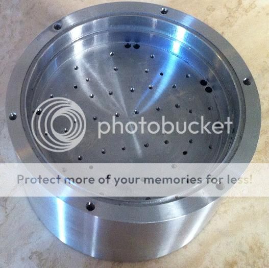
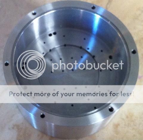
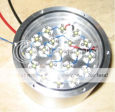
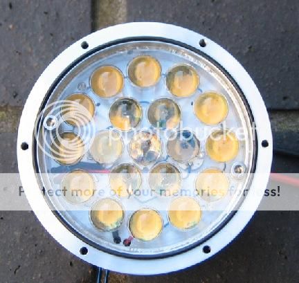
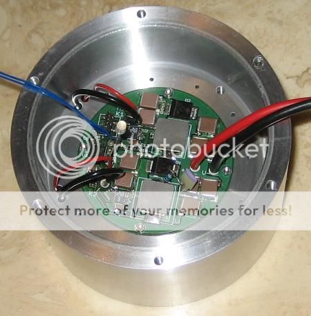
To do this I've decided to build a rather large unit based on 19-xpg's. I'll use 7 to construct the dip-beam and 12 to form the main beam. Each LED will have its own aspheric lens and the relative position of the LED to the lens centre will influence the direction in which the image of the LED is projected. The LEDs are placed close to the focal point of the lens in order to create a sharp cut-off which will allow the dip-beam to be set up to prevent excessive spill reaching on-coming traffic. Each of the 7 LEDs used to form the dip-beam will point in a specific direction in order to build the desired beam shape. Main beam is formed by 12 LEDs all projecting in the same direction.

It is a grand plan with the potential to put out some serious lumens (19 xpgs at 1.5A each). With this number of LEDs available I don't need to choose ultra-high output cool-white tints, so I've opted for the softer warm tints which I prefer.

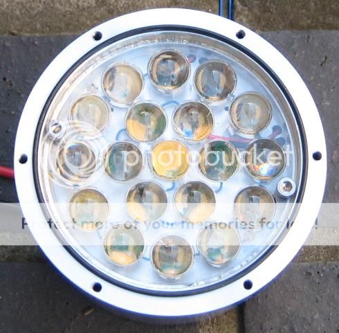
The first part of this build is focused the lens (sorry for the pun). Mounting 19 lenses was proving to be rather tedious, so I turned to a custom home-cast compound lens: 19 little (12mm) aspherics arranged in concentric circles. Here is a picture.

Lens1_small.jpg


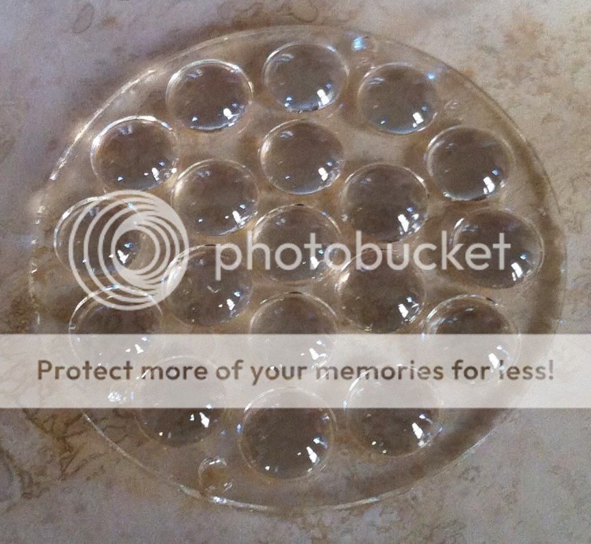
This lens isn't small - the outside diameter is 70mm.
It was made by making a mould of a 12mm aspheric lens then copying it multiple times until I had enough lenses. These were then arranged in a pre-drilled template to make the final mould. The lens was then cast in this mould using clear casting resin with the same refractive index as the original lens. The finished product is not quite projection quality, but it is possible to obtain a projected image of the LED with a well-defined edge, giving me the sharp cut-off I was after.

I'll post more details as I progress - next installment is the housing. Drawings are done and with a local machine shop.
 

Steve K

Flashlight Enthusiast
Joined
Jun 10, 2002
Messages
2,786
Location
Peoria, IL
pretty wild! I had no idea that it was even feasible to produce this sort of optic at home. I'm curious to learn how you are controlling the position of the LEDs in order to get the light pointed in the desired direction.

I'll admit to assuming that this was a dynamo light, and wondering how all of those XP-Gs would be powered. It wasn't until I read that you will drive them at 1.5A that I finally realized that this was battery powered. I'm a little disappointed that there wasn't a secret technique that would let me use this with my dynamo. :)
 

BillyNoMates

Newly Enlightened
Joined
Jan 16, 2009
Messages
144
Location
Bristol,UK
I'm curious to learn how you are controlling the position of the LEDs in order to get the light pointed in the desired direction.

For this iteration, the LEDs are mounted on individual MCPCBs and will be fixed to the base-plate with small machine screws. The drilling diagram I sent to the machine shop will get the holes in the ideal positions that I have already settled on. There is a little bit of clearance around each hole in the MCPCB so I will be able to make small adjustments to each LED location with the aid of a template I made (this is just a thin disc with holes drilled where I want the LEDs located. I I do another version, I will probably make a special MCPCB with the LEDs soldered in the right places which will make the assembly easier (fewer holes and less fiddling). The lens has two holes for screws to locate it to the base plate to keep it aligned with the LEDs below it.

It wasn't until I read that you will drive them at 1.5A that I finally realized that this was battery powered. I'm a little disappointed that there wasn't a secret technique that would let me use this with my dynamo.

Yes battery power here (no secret dynamo solution).
 

AnAppleSnail

Flashlight Enthusiast
Joined
Aug 21, 2009
Messages
4,200
Location
South Hill, VA
It looks like each lens is in the same plane. To me this indicates that turning off some lights would only slightly change the beam shape. Are they actually 'aimed' to produce a pattern, or are they all co-linear?
 

BillyNoMates

Newly Enlightened
Joined
Jan 16, 2009
Messages
144
Location
Bristol,UK
It looks like each lens is in the same plane. To me this indicates that turning off some lights would only slightly change the beam shape. Are they actually 'aimed' to produce a pattern, or are they all co-linear?

Yes, each lens is in the same plane and regularly spaced. The beam pattern is produced by offsetting each LED with respect to the centre axis of each lens.

Consider a LED focused onto a wall producing a clear image of the die. Light from each part of the die comes to focus at a specific location - top edge of die is imaged at bottom edge of image. A bigger die would produce a bigger image and a smaller die would produce a smaller image etc etc. Offsetting the LED with respect to the lens centre has the effect of moving the image on the wall. I use this technique to build the beam shape I am after - all the LEDs used in the high-beam are set lower than those used for the low-beam and therefore their image is projected higher.

I've tested this on a smaller scale (two LEDs) and it works a treat. As long as I can get the LEDs lined up accurately, I should get the effect I am after.
 

AnAppleSnail

Flashlight Enthusiast
Joined
Aug 21, 2009
Messages
4,200
Location
South Hill, VA
I've tested this on a smaller scale (two LEDs) and it works a treat. As long as I can get the LEDs lined up accurately, I should get the effect I am after.

Neat! So it's like projectors using lamp position to create a cutoff. I would have approached it from a different direction that would require much more exacting positioning of the lenses. Good luck! Let us know how it turns out.
 

BillyNoMates

Newly Enlightened
Joined
Jan 16, 2009
Messages
144
Location
Bristol,UK
The housing arrived from the machine shop this morning and I'm really pleased with it.

The front view has all 38 holes drilled and tapped for M1.6 machine screws to locate the individual LED MCPCBs. The lens sits on the shoulder above the base plate and is located by two M3 screws. There is a groove in the top edge for an o-ring and 6 M3 holes to locate the front cover.

HousingFront_small.jpg


The rear view is shown below. It is a little bit deeper than I need, but as this is a first prototye, I thought it would be better to have more space than I need. The driver will sit above a 2mm recess and will be screwed to the base plate by 4 M1.6 screws. The driver has components on the under side (FETs, thermistor and other passives) and these will heatsink to the body via a compressible thermal interface material sitting in the recess. This side also has a groove for an o-ring and 6 M3 holes for the rear lid.

HousingRear_small_zps557f79bf.jpg


I'll start the assembly tonight and get some idea about the alignment of the LEDs and lens.
 

BillyNoMates

Newly Enlightened
Joined
Jan 16, 2009
Messages
144
Location
Bristol,UK
I have made some progress on the assembly. The LEDs are now fitted and (more-or-less) aligned with the lens.

The image below shows the LEDs in place:
LEDSsmall_zpsd5d96e97.jpg


The image below shows a view of the front of the light taken at an angle where only one of the LEDs is aimed (the centre one).

FocussedLEDS2_zpsf0b5d9d3.jpg


This next image is taken at a different angle and shows the outer ring of LEDs:
FocussedLEDS1_zps882b95f1.jpg


Notice that in the latter plot the three LEDs in the centre are not visible as they form the lowest part of the dip-beam. There is some overlap between the main beam and dip beam at the upper edge of the dip-beam (by design) which is why the two LEDs above and two LEDs below the centre three are partially visible.

I need to do a little more work before I can test the beam pattern, so I will report back in a few more days....
 

BillyNoMates

Newly Enlightened
Joined
Jan 16, 2009
Messages
144
Location
Bristol,UK
Although the driver isn't ready yet, I wanted to run some beam tests to see if I was getting the pattern I was expecting. As I explained in one of the posts above, the beam pattern is roughly triangle shaped, with 7 LEDs forming the low beam and 12 LEDs forming the high beam. I spent some time on the weekend playing with some resistors and an automotive battery in order to get the LEDs to illuminate.

The low beam is constructed from a lower row of 3 LEDs arranged to project side-by-side, with a second row made from 2x two LEDs side-by-side. The doubling up of the LEDs for the upper row puts out more light intensity for the part of the beam that is pointing further down the road.

The high beam uses 12 LEDs all projecting partially above the upper part of the low-beam and partially overlapping it, however because these LEDs are rotated by 30degrees between neighbours they will form a rounder image. The sketch below shows what I'm trying to describe: Blue shows low beam, red shows high beam.

BeamPattern_zpsb03ca0ea.png


The picture below shows the image of the low beam projected onto a flat wall a couple of metres distant:

LowBeam_zps6ac55a83.jpg


This image shows the low-beam is quite close to what I wanted - three die images side-by-side in the lower row with a narrower, brighter top row made from two doubled up die side-by-side. The cut-off at the top edge of the low-beam is quite abrupt which should help to reduce glare if the low beam is angled down below eye-level of on-coming motorists.

The image below shows both low-beam and high-beam on together:

HighBeam_zpsf3cf7bff.jpg


This image shows that the lower row of LEDs from the main beam is still visible, indicating very little of the main beam output is causing spill close-in. The hot-spot from the high beam has swamped the upper part of the low-beam and the sharp cut-off is no longer obvious indicating that there is significant output above the extent of the low beam.

I am unsure about the amount of overlap in this prototype. I think some overlap is needed, but there will be a trade-off between the down-tilt applied to the low-beam and the amount of light radiated above the horizon. In this first instance I've gone for a slightly lower main beam to favour a relatively shallow tilt angle for the low-beam. I'll have to assess this choice over a few weeks of riding (when the driver and battery are ready) before I can make a judgement about its effectiveness.

I may also have to make adjustments to the position of the lens to try to improve the focus - however, the current setup is quite close to what I am after so I'm not sure if there is any benefit in tweaking things for marginal improvements.
 

VegasF6

Flashlight Enthusiast
Joined
Dec 5, 2007
Messages
1,449
Location
Las Vegas
This is quite a grand project, very neat things you have done with casting your own lens and such.

Aren't you concerned with trying to keep ~85 watts of leds cool? I did see a brief mention of thermistor which I guess you plan to actively monitor temperature and control power with such, but this is such a massive amount of heat I can't imagine your housing is capable of keeping up even at half that power. Did you do any sort of thermal modeling or even back of a napkin calculations?
I see your leds are already mounted now, but have you considered pumping 85 watts of heat into your housing via power resistors or peltier junction or some other external heat source and blowing air across it at ~5mph or whatever you think is realistic for biking and see what happens?

Hope that didn't come off as too negative, just trying to get a grasp on the reality of it.
 

BillyNoMates

Newly Enlightened
Joined
Jan 16, 2009
Messages
144
Location
Bristol,UK
This is quite a grand project, very neat things you have done with casting your own lens and such.

Aren't you concerned with trying to keep ~85 watts of leds cool? I did see a brief mention of thermistor which I guess you plan to actively monitor temperature and control power with such, but this is such a massive amount of heat I can't imagine your housing is capable of keeping up even at half that power. Did you do any sort of thermal modeling or even back of a napkin calculations?
I see your leds are already mounted now, but have you considered pumping 85 watts of heat into your housing via power resistors or peltier junction or some other external heat source and blowing air across it at ~5mph or whatever you think is realistic for biking and see what happens?

Hope that didn't come off as too negative, just trying to get a grasp on the reality of it.

You are quite right to draw attention to the problem of thermal management - don't worry about being negative!

To be honest, I don't intend to use the light at full power very often, probably saving the brightest setting for parts of my route where I really need to see the road in detail (on my regular commute there is a tree-covered, steep and twisty descent that often has gravel/stones washed into the road after heavy rain, or the occasional branch brought down by high winds).

In the riding conditions I generally encounter in the "dark months" I have estimated that the housing should be able to dissipate about 25W at approx 30km/h with a 10C air temp (I used an online calculator to estimate this value). Given mass of the housing and the estimated cooling rate from the forced convection, I think I'll get between 3 and 5 mins on full power.

Once the temperature gets too high (as measured by the aforementioned thermistor) the high mode is disabled, if the light continues to get hot (because it is left on and isn't being cooled, then the light will drop to minimum power to protect itself.

I've assembled the LEDs into the unit, so any temperature testing will be using the LEDs as the heat source - I need to wait until I've finished the driver + controller before I can plan to do any heat testing.
 

BillyNoMates

Newly Enlightened
Joined
Jan 16, 2009
Messages
144
Location
Bristol,UK
Check out this guy's water cooling. Assuming no heat transfer to the environment AND no heat capacity of the metal, his 1L water heatsink heats at 3.6C per minute when running at 300W.
Yes, that is awesome isn't it? Water cooling opens up all sorts of possibilities for super high power bike lights!. However, for me I'll have to rely on backing off the power if things get too hot. Perhaps next time......
 

BillyNoMates

Newly Enlightened
Joined
Jan 16, 2009
Messages
144
Location
Bristol,UK
I have made a little more progress on this project now - the driver has been built and installed. Functionally everything is working OK, but I need to spend more time on the software to implement all the features I want, such as temperature monitoring, voltage monitoring, and different modes etc.

Here is a picture showing the driver installed:
Driversmall.jpg


Details:
This is a custom boost converter designed to deliver 1.5A at upto 40V from a 4S LiIon pack (14.8V) - sufficient to drive a string of 12 XP-Gs. There are two drivers on a single PCB on has the voltage limit set to 25V (for the 7-XPG string making up the dip-beam) and the other has the limit set to 40V for the longer 12-string forming the main beam.

I have found in the past that a 3x change in power between output levels gives a good increase in light output (doubling the output power doesn't quite achieve the desired effect). I have continued the same theme here and used a combination of analogue and PWM dimming to achieve the range in output power. Max setting uses the drivers at 100% duty cycle pushing 1.5A. Tne next level down drops the current to 0.5A, keeping to the 100% duty cycle. The lower levels are achieved by PWM at this lower current level, 1/3, 1/9 and 1/27 settings.

The driver controls are independent, but there operation will be sequenced into specific modes by a micro-controller. I'm keeping the same User Interface that I have used on my previous designs with the modes arranged into a linear order where a 'double-click' on the push-switch will move up in power, a 'single-click' will move down in power. I will probably have 4 power levels for the dip-beam with another two levels using both dip and main outputs. A 'long press' will switch between standby and active operation.

I'll also include a couple of flashing modes, but rather than simply being hard flashes, these flash modes will be 'soft', using a PWM ramp to fade the power up and down smoothly. I'm doing this to minimise the actual off-time of the light - should be interesting to see what it looks like (it is intended for urban routes).

I still need to do more work on the micro-controller SW to implement the thermal controls and I need to source a battery so I'll report back the next time there is significant progress
 

BillyNoMates

Newly Enlightened
Joined
Jan 16, 2009
Messages
144
Location
Bristol,UK
Any updates?
Yes, I must post some more stuff about this project - the lack of the usual beam shots is a bit of an omission.

I have been using this successfully through the winter and dark evenings and I have been generally very pleased with the result. Here is a summary of my experience:

i) High-beam / Low-beam transition is excellent - the transformation in the illumination pattern really enhances the extra light output.
ii) High-beam drive levels. I currently run two drive levels for high beam, 0.5A and 1.5A. The driver only allows the highest output level if the battery is >60% charged, but to be honest, the difference in the perceived light level is a little disappointing. I am considering changing this setting for a single high-beam mode, with perhaps a 1A drive level. There really doesn't seem to be any point in having two high-beam settings.
iii) Low-beam pattern: I may need to change the low-beam pattern, current set up has too much light close in an not enough further away. I may drop the lower three tiles from the pattern and swap the upper row to a combination of XP-Gs and XP-Es - the smaller die sizes of the latter should help with the light intensity further away.
iv) Focus - I may try shimming the lens to improve the cut-off. This will help in aiming the light a bit better.
v) Low-beam spill - the glare from the low-beam is quite acceptable (I think). For on-coming traffic (and cyclists on cycleways - these are much closer than traffic) the light looks 'bright', but I don't think it is offensive - very much like a car headlight on dip-beam. I think the choice of warm tints helps with this a lot. I think this light is much better than the typical XM-L in a conical reflector that I have to put up with from other cyclists.

I'll try and take some more photos over the weekend showing the set-up on the bike and hopefully some representative beam shots.
 
Top