

Techjunkie
Enlightened
I was contacted by another member to see if I could improve a custom light he'd just bought. He wanted higher output and better throw. We agreed on a mod approach and he sent me the light. I underestimated the amount of effort required to do what we discussed - so much so that I felt the effort deserved documentation in its own thread, video and all...
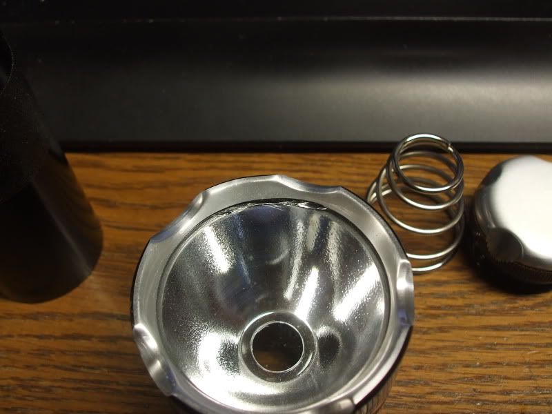
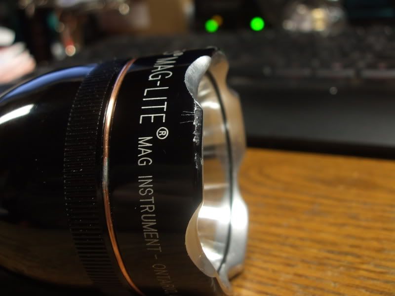
I should have known this light was going to give me trouble from the start... it had taken a knock before getting to me and the bezel put up a really good fight coming off before I could replace the lens which had been crushed at the edge:


Luckily, freezing the head (and some muscle) provided the solution to unscrewing the bezel and freeing the reflector and lens. Getting that bezel off was necessary not only to repair the lens, but also to use the Mag Rebel reflector he wanted. It nearly put an end to the entire project before it began.
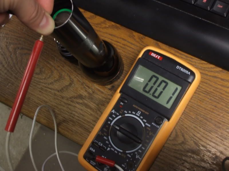
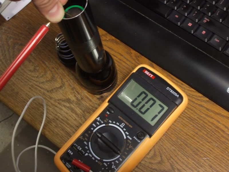
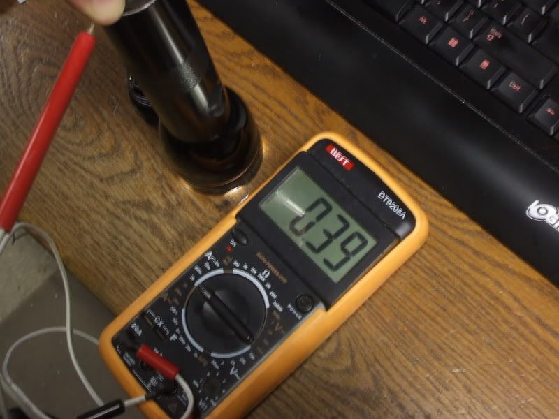
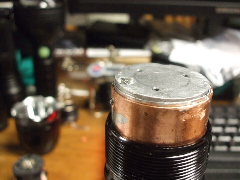
Next problem to tackle were the drive current issues. The source of the problem turned out to be two-fold: The ground wire wedged between the Al heatsink and the Cu shim had too much wiggle room. The ground path needed to be improved. Here were the original current measurements I was getting on my DMM, using an IMR26650 cell:
 |
|  |
| 
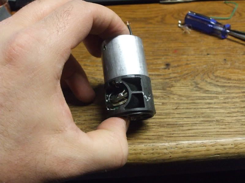
Temporarily fixing the ground issue only produced unreliable current readings averaging about double those above, and never more than 1.5A on high. That revealed a weak path to battery positive across the switch... the switch could still serve to operate the driver, but would have to be bypassed for the LED path. That meant getting the switch assembly out without damaging it. It would have been easier if it had been held in with a pin like the heatsink and shim, but the assembly had been epoxied to the tube and snapring:

In order to achieve focus with the 40mm deep Rebel reflector and still thread the head on passed the gasket, the heatsink would need to be recessed more, which meant relocating the drivers. The pedestal had to go not only for height reasons, but also because of the drive current we were aming for - 4.4A.
Here's what we took out:

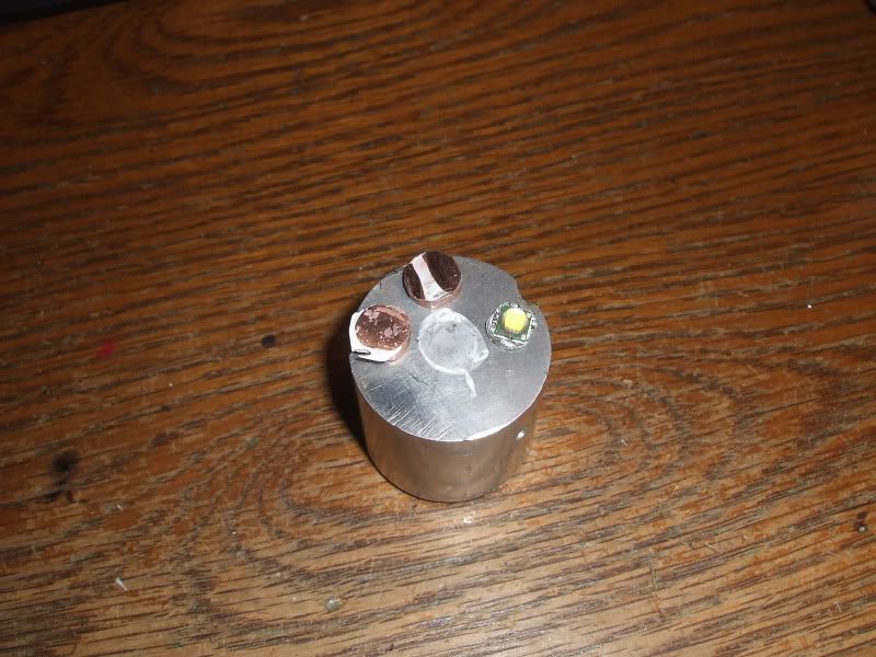
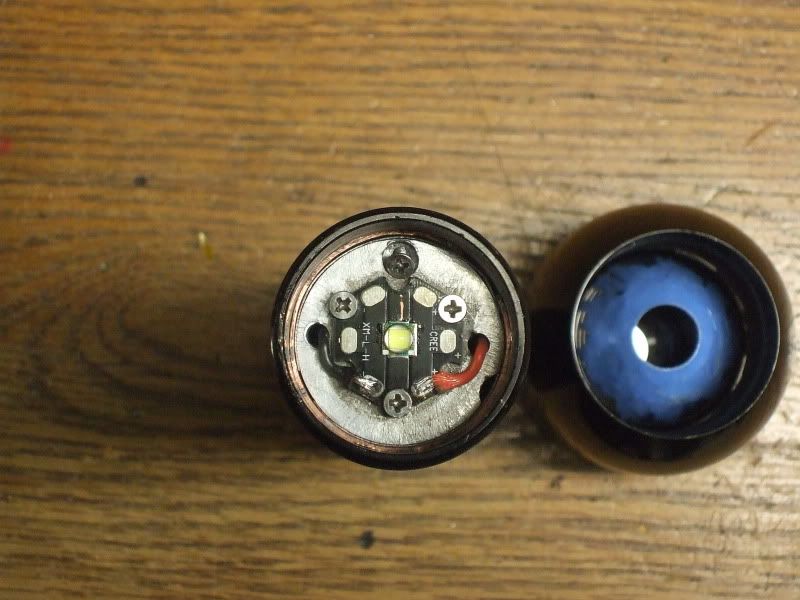
And here's what went back in...
I cleaned and buffed the surface for mounting a new XML on 20mm star and drilled and tapped holes for mounting. I also fitted an aluminum sheet metal shim to go between the HS and the copper shim, and then tapped a hole on a diagonal through the HS and both shims, to serve as a set screw to replace the one absent from the switch housing and provide a reliable ground connection.


Eventually, two more holes would be drilled straight through for LED leads, and finally another hole tapped on the bottom to provide a ground screw to attach driver ground to.
But before that, a new driver stack had to be made and fit inside the switch assembly, so the HS could be dropped to the necessary depth.:

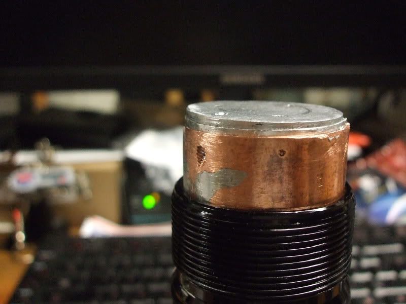
Here's a peak at the finished installation, after cleaning out the tube with a brake hone, and greasing both sides of both shims and the HS with HS grease:

The fit is so snug that it took some hammering with a section of PVC to get everything into the tube before setting the set/ground screw. Improved heatsinking and electrical connections... check.
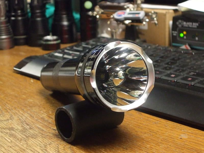
The finished product, with bezel fully seated and switch button centered under boot:

And finally, a demonstration video of the drive currents:
I should have known this light was going to give me trouble from the start... it had taken a knock before getting to me and the bezel put up a really good fight coming off before I could replace the lens which had been crushed at the edge:
Luckily, freezing the head (and some muscle) provided the solution to unscrewing the bezel and freeing the reflector and lens. Getting that bezel off was necessary not only to repair the lens, but also to use the Mag Rebel reflector he wanted. It nearly put an end to the entire project before it began.
Next problem to tackle were the drive current issues. The source of the problem turned out to be two-fold: The ground wire wedged between the Al heatsink and the Cu shim had too much wiggle room. The ground path needed to be improved. Here were the original current measurements I was getting on my DMM, using an IMR26650 cell:
 |
|  |
| 
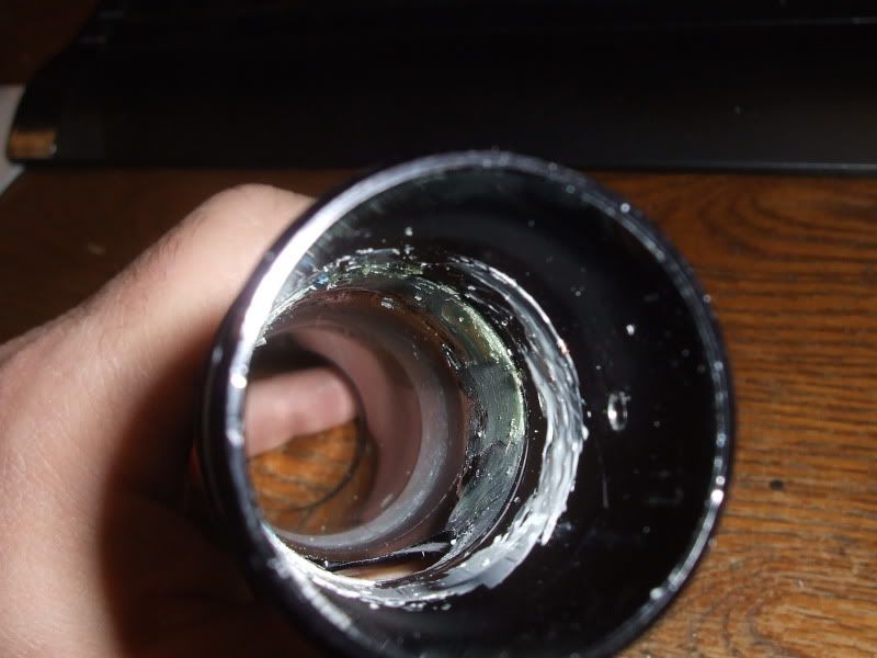
Temporarily fixing the ground issue only produced unreliable current readings averaging about double those above, and never more than 1.5A on high. That revealed a weak path to battery positive across the switch... the switch could still serve to operate the driver, but would have to be bypassed for the LED path. That meant getting the switch assembly out without damaging it. It would have been easier if it had been held in with a pin like the heatsink and shim, but the assembly had been epoxied to the tube and snapring:
In order to achieve focus with the 40mm deep Rebel reflector and still thread the head on passed the gasket, the heatsink would need to be recessed more, which meant relocating the drivers. The pedestal had to go not only for height reasons, but also because of the drive current we were aming for - 4.4A.
Here's what we took out:
And here's what went back in...
I cleaned and buffed the surface for mounting a new XML on 20mm star and drilled and tapped holes for mounting. I also fitted an aluminum sheet metal shim to go between the HS and the copper shim, and then tapped a hole on a diagonal through the HS and both shims, to serve as a set screw to replace the one absent from the switch housing and provide a reliable ground connection.
Eventually, two more holes would be drilled straight through for LED leads, and finally another hole tapped on the bottom to provide a ground screw to attach driver ground to.
But before that, a new driver stack had to be made and fit inside the switch assembly, so the HS could be dropped to the necessary depth.:
Here's a peak at the finished installation, after cleaning out the tube with a brake hone, and greasing both sides of both shims and the HS with HS grease:
The fit is so snug that it took some hammering with a section of PVC to get everything into the tube before setting the set/ground screw. Improved heatsinking and electrical connections... check.
The finished product, with bezel fully seated and switch button centered under boot:
And finally, a demonstration video of the drive currents:
 Dont think nothing was meant by this oldlumens. Sounds like he intended to mod it before he even got it. After all you sold it cheap considering all the work that was put into it. Keep your amazing work going and post up your mods oldlumens. I have enjoyed them.:thumbsup:
 So I hit reply again, double post.


