600 Watt Short Arc M-134 Cannon Light - INFANT AN/ASQ-132

BVH

Flashaholic
Joined
Sep 25, 2004
Messages
7,023
Location
CentCalCoast
Re: 500 Watt Short Arc M-134 Cannon Light

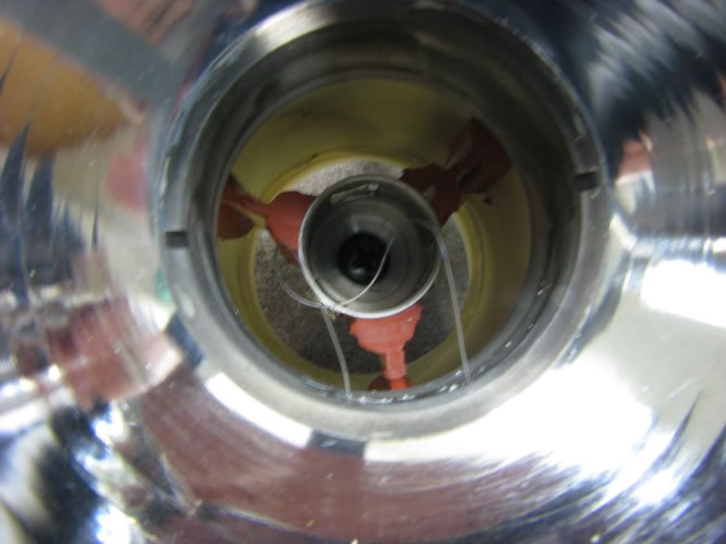
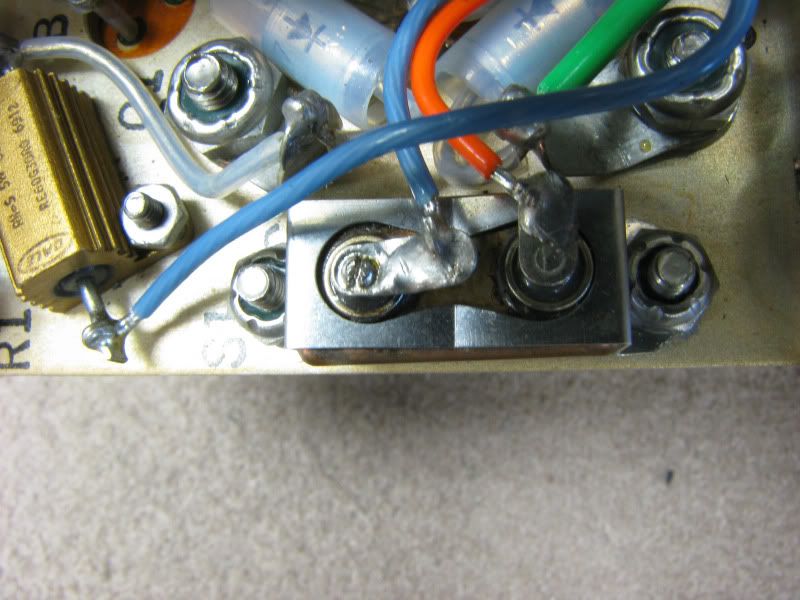
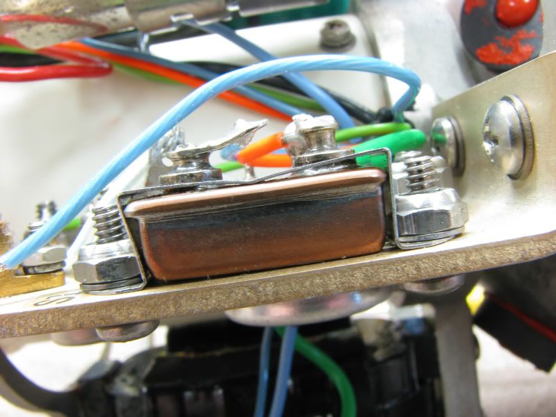
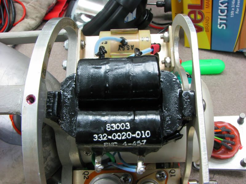
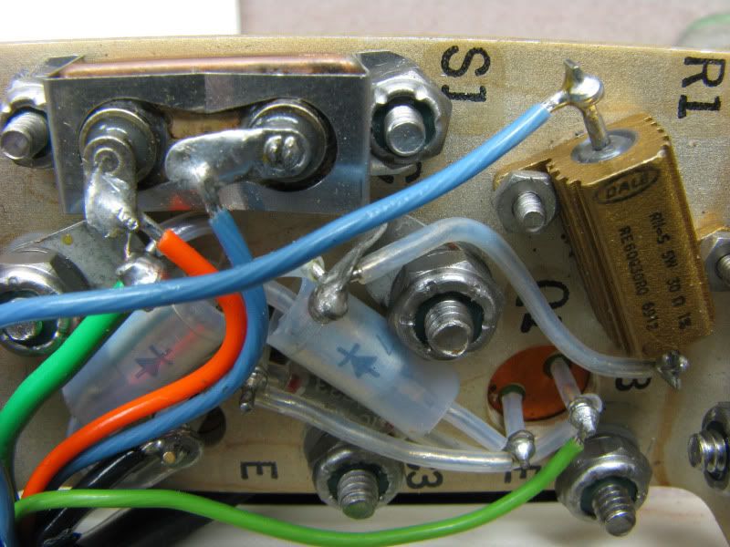
Good question on what that part is. One of the 9 connection wires lands on it. It's very thin so I don't think anything moves inside it. The big green box is the igniter. I have no reason to suspect that any ballast parts are bad. ARC thought by looking at the pics of the bulb that it might have lost it's seal. But they can't definitely tell nor dedicate time and help to me until the beginning of June.

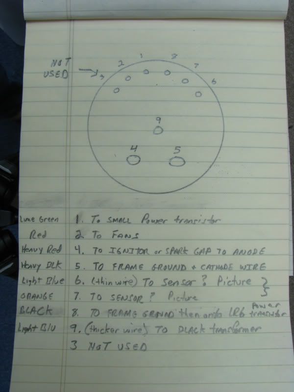
EDIT Add. I should mention that the OEM connection cable that came with it is, of course, is 9 pin on the light end but it's a 15 pin on the other end. I haven't rung out the cable yet so maybe a bunch are not used or some are connected together at the 9-pin end.
 
Last edited:

FRITZHID

Flashlight Enthusiast
Joined
Jun 20, 2011
Messages
2,500
Location
Icelandic wastelands of Monico, WI
Re: 500 Watt Short Arc M-134 Cannon Light

the large green box Could be the spark gap.... i've seen them that size, but only on larger systems.... usualy designed for 5kW pulsed CO2 Lasers.... BUT being this is a Mill Spec device, over compensation is NOT uncommon. maybe disconnect it and test witn DMM? if it's open, i'd say 85% thats what it is... (without looking right at it and following the wires thru the device) but it does look like it connects to that smaller white cap mounted near it.


Side Note: was watching some old Voyager episodes and the name "500w Photonic Cannon" pop'd into my head for this lil gem of yours. ;)
 
Last edited:

FRITZHID

Flashlight Enthusiast
Joined
Jun 20, 2011
Messages
2,500
Location
Icelandic wastelands of Monico, WI
Re: 500 Watt Short Arc M-134 Cannon Light

Curiosity is getting the best of me. Why do some discharge tubes like flashtubes have that wire that wraps around it or goes end to end?

that is the "trigger" wire... it's used when the HV starting surge kicks. on flash tubes, a Flyback xformer is the source of the HV pulse and unlike the auto HIDs, it only causes a "static" charge, which travels through that wire and ionizing the xenon causing the main charge from the "low" voltage high current cap to discharge across the tube. on XSA lamps, i'd guess it's just an added measure to insure the trigger spark gets the lamp started using less voltage then would normally be needed to initially jump the gap by ionizing right through the quartz itself.
 

BVH

Flashaholic
Joined
Sep 25, 2004
Messages
7,023
Location
CentCalCoast
Re: 500 Watt Short Arc M-134 Cannon Light

There is also another "trigger wire'ish" half loop of wire that comes up from the reflector housing directly underneath the stem on the bulb, half loops around only the bottom half of the stem and goes back down to the reflector housing. I've never seen this before. It does not offer any type of support so it's not structural. Any ideas?

2ndtriggerwire.jpg
 

FRITZHID

Flashlight Enthusiast
Joined
Jun 20, 2011
Messages
2,500
Location
Icelandic wastelands of Monico, WI
Re: 500 Watt Short Arc M-134 Cannon Light

thats a ground wire. reduces static charge around the envelope and may reduce some (tho not alot) of the ozone. i've seen these on some high voltage glass discharge tubes of various types. helps lessen degradation of the tube and eliminates the static build up between bulb and chassis. (usually only found in systems with high potential in a confined package. i've had some gas lasers with those in them)
 

BVH

Flashaholic
Joined
Sep 25, 2004
Messages
7,023
Location
CentCalCoast
Re: 500 Watt Short Arc M-134 Cannon Light

Should it be touching the bulb or just close to it when I go to re-assemble? I can't remember how close it is to the trigger wire right now.
 

FRITZHID

Flashlight Enthusiast
Joined
Jun 20, 2011
Messages
2,500
Location
Icelandic wastelands of Monico, WI
Re: 500 Watt Short Arc M-134 Cannon Light

well, having never seen one on a XSA persay, i'd have to say NOT touching the trigger wire for sure, and bulb contact.... well i'd say assemble it and see how close it is to the envelope,... if its looks like it's going to touch no matter what, i'd have to say it's sapposed to, if it looks like it's close but can go eather way, i'd say play it safe and keep it off.
 

BVH

Flashaholic
Joined
Sep 25, 2004
Messages
7,023
Location
CentCalCoast
Re: 500 Watt Short Arc M-134 Cannon Light

Yes, I guessed it should definitely not touch the trigger wire. I assume it would instantly melt.
 

BVH

Flashaholic
Joined
Sep 25, 2004
Messages
7,023
Location
CentCalCoast
Re: 500 Watt Short Arc M-134 Cannon Light

OK, the mystery is getting easier by process of elimination. First, only 8 of the 9 pins are used. #3 is not used. Also, wires #6 and #7 are directly connected thru this "sensor" (see pics) and go nowhere else - wire from Pin 6 comes from the connector, lands on one of the sensors' terminals and wire #7 is connected to the sensors' other terminal and goes directly back out to pin #7. The sensor is not connected to anything else by wires. It does, however ride on the frame but I don't know if this is just the way it's mounted or if it is actually grounded. So I'm guessing this is to trigger something else in the INFANT system and not used to run the light. Maybe an overheat condition sensor? So....3 Pins out of 9 could possible be defined now. One for the Anode and one for the Cathode. 5 out of 9. One black wire Pin for frame ground. 6 out of 9. Somethings got to power the transformer - light blue (thicker) wire, so there's another Pin - 7 out of 9. One pin to the cooling fans - 8 out of 9. So what is the purpose of the small Lime green wire that's going to the power transistor? Here's a diagram of the 9 Pin connections.

Pinouttext.jpg


Sensortopview.jpg


Sensorsidefiew.jpg


Transformerinandout.jpg
 
Last edited:

FRITZHID

Flashlight Enthusiast
Joined
Jun 20, 2011
Messages
2,500
Location
Icelandic wastelands of Monico, WI
Re: 500 Watt Short Arc M-134 Cannon Light

pins 6+7 i think are thermal cut off sensor..... easy to test... pull it off, throw a DMM on it, if reads 0 ohms *or there abouts* apply heat slowly and see if it opens
8 ground to ignitor and control circuitry.
9 would then be iginitor trigger (what voltage in, is anyone's guess.)
and pin 1.... thats a tough one to guess at... but i'd have to say.... maybe strobe trigger, or perhaps variable brightness? whats that smaller Transistor also connected to?
 

BVH

Flashaholic
Joined
Sep 25, 2004
Messages
7,023
Location
CentCalCoast
Re: 500 Watt Short Arc M-134 Cannon Light

All sounds plausable except the possible strobe, only because of the usage of the light. What would be the purpose of strobing a target? Well, if the ground based enemy was wearing NVG and could easily see the light, they could possibly fire on the chopper so maybe it's not out of the question. Strobing might incapacitate. Variable brightness. seems possible. Will investigate the small transistor and report back.

Not only does the pinout need to be sorted out, but appropriate applied Voltage needs to be determined. So many variables. I've got both INFANT manuals coming. The -1 which is mostly text in operation and maint of the entire system including pages on the light and -2 which is mostly electrical diagrams. Hopefully, between both, all questions should be answered. But it is fun trying to figure it out.

What is a fly-back transformer and what does it do?
 

BVH

Flashaholic
Joined
Sep 25, 2004
Messages
7,023
Location
CentCalCoast
Re: 500 Watt Short Arc M-134 Cannon Light

The lime green wire is Pin 1 and goes first to the small PT. From the other terminal of the small PT, it divides two directions.

Path 1 is: From small PT to a diode then to brass colored resistor, out the resistor to the same input terminal on the transformer as the Pin #9

Path 2: From the output of the small PT to the big PT, then divides - goes thru a diode and back to frame ground where Pin # 8 lands. The other path is to terminal #2 on the transformer. I'm thinking terminal #2 on the transformer is the ground leg on the input.

I forget, does current flow against the arrow in the diode or with the arrow? Trying to figure out which way current in the green wire is going. I now think I've got it backwards and that the green wire conveys current out to Pin 1, not from Pin one.

closeupofwirelandings.jpg
 

get-lit

Flashlight Enthusiast
Joined
Jan 22, 2007
Messages
1,216
Location
Amherst, NY
Re: 500 Watt Short Arc M-134 Cannon Light

The arrow ALWAYS points toward the flux capacitor.
 

FRITZHID

Flashlight Enthusiast
Joined
Jun 20, 2011
Messages
2,500
Location
Icelandic wastelands of Monico, WI
Re: 500 Watt Short Arc M-134 Cannon Light

All sounds plausable except the possible strobe, only because of the usage of the light. What would be the purpose of strobing a target? Well, if the ground based enemy was wearing NVG and could easily see the light, they could possibly fire on the chopper so maybe it's not out of the question. Strobing might incapacitate. Variable brightness. seems possible. Will investigate the small transistor and report back all i can say is it's not a main power control transistor, not if it connects to a 2nd larger "Q". i'd have to say it eather controls brightness or perhaps its used to pulse the lamp as needed, that way it's not "constant on". any light, just like a laser, makes you a target, whether IR or visible.

Not only does the pinout need to be sorted out, but appropriate applied Voltage needs to be determined. So many variables. I've got both INFANT manuals coming. The -1 which is mostly text in operation and maint of the entire system including pages on the light and -2 which is mostly electrical diagrams. Hopefully, between both, all questions should be answered. But it is fun trying to figure it out.yes, that will be VERY helpful! (i can't wait to see it, i'm just as curious as you are!)

What is a fly-back transformer and what does it do?
a flyback transformer it whats used in many electronics where High Freq/High Voltage is needed, theres large ones in TV's, they can be ID'd by the LARGE WIRE that comes off the outside of the back of the picture tube down to the board, are usualy large odd "towerish" shaped devices with the output wire coming out the top. they use multiple lower voltage primary coils at high rotating pulse rates to a single high voltage secondary coil. between the flyback and the "charging cap", it's the whining you hear in a TV when it starts up. the whine you hear from a camera flash is not exactly the same, they still use something similar to get the lo-V DC batt power up to the 600-800v the tube needs and that requires lo-V DC changed to AC to step it up, then it's rectified and stored in a large Cap (2200 or more uF) *WARNING, do NOT use screwdriver to discharge strobe cap while people are in room and not pay'n attn!, this may cause parent and/or other relations to jump wildly and then proceed to hit you* that cap is directly connected to the anode and cathode of the strobe tube, then theres a smaller cap on the board that is connected through the shutter control on the camera, and THAT closes the circuit between it and the small flyback transformer that causes a low current 30K volt static charge to shoot across the trigger wire on the tube and ionize the gas enough to where the large cap "pops" across the tube resulting in flash blinded persons anywhere near by. :D http://en.wikipedia.org/wiki/Flyback_transformer

The lime green wire is Pin 1 and goes first to the small PT. From the other terminal of the small PT, it divides two directions.

Path 1 is: From small PT to a diode then to brass colored resistor, out the resistor to the same input terminal on the transformer as the Pin #9

Path 2: From the output of the small PT to the big PT, then divides - goes thru a diode and back to frame ground where Pin # 8 lands. The other path is to terminal #2 on the transformer. I'm thinking terminal #2 on the transformer is the ground leg on the input.

I forget, does current flow against the arrow in the diode or with the arrow? Trying to figure out which way current in the green wire is going. I now think I've got it backwards and that the green wire conveys current out to Pin 1, not from Pin one. the tip of the triangle and the | are the NEG side, flat side of the triangle is the POS.

closeupofwirelandings.jpg
 

bshanahan14rulz

Flashlight Enthusiast
Joined
Jan 29, 2009
Messages
2,819
Location
Tennessee
Re: 500 Watt Short Arc M-134 Cannon Light

I think S1 is a temp sensor too.

Also, three legs of transistors often called collector, emitter, and base. I think that the collector terminal is just the case of the transistor, and probably is at ground potential? The base is kind of like the trigger pin.
 
Last edited:

FRITZHID

Flashlight Enthusiast
Joined
Jun 20, 2011
Messages
2,500
Location
Icelandic wastelands of Monico, WI
Re: 500 Watt Short Arc M-134 Cannon Light

I think S1 is a temp sensor too.

S1 signifies SWITCH #1, not sensor, hence why i figured a temp switch. prob doesent shut the light down but just sets off a warning light and buzzer in the cockpit of the huey letting them know it SHOULD be shut down... COULD also just turn the cooling system on and off as needed, but i find that far more unlikely.
 

BVH

Flashaholic
Joined
Sep 25, 2004
Messages
7,023
Location
CentCalCoast
Re: 500 Watt Short Arc M-134 Cannon Light

Me too as this is such a small volume of space inside the light chamber and there is no direct cooling. Inside fan recirculates sealed system air and sends it over a radiator which is then cooled by fan number 2 which draws in outside air. Without both fans running full time, it would be tremendously hot inside the can.
 

FRITZHID

Flashlight Enthusiast
Joined
Jun 20, 2011
Messages
2,500
Location
Icelandic wastelands of Monico, WI
Re: 500 Watt Short Arc M-134 Cannon Light

is there a clear lens for this as well? or just the IR unit? if there IS a clear lens, and the canister is well sealed, something that may help it all around in future use, is to purge the inside with N2, this will help with moisture, cooling (since N2 is a larger molecule) and with the absence of O2, the production of ozone will be less, and ozone can be hard on the insulation and other parts inside being a strong oxidizer. (just a thought that popped into my head as i opened a bag of chips today and remembered that they purge food bags with N2 to reduce stale food issues as they sit on the shelves)
 
Top