

Techjunkie
Enlightened
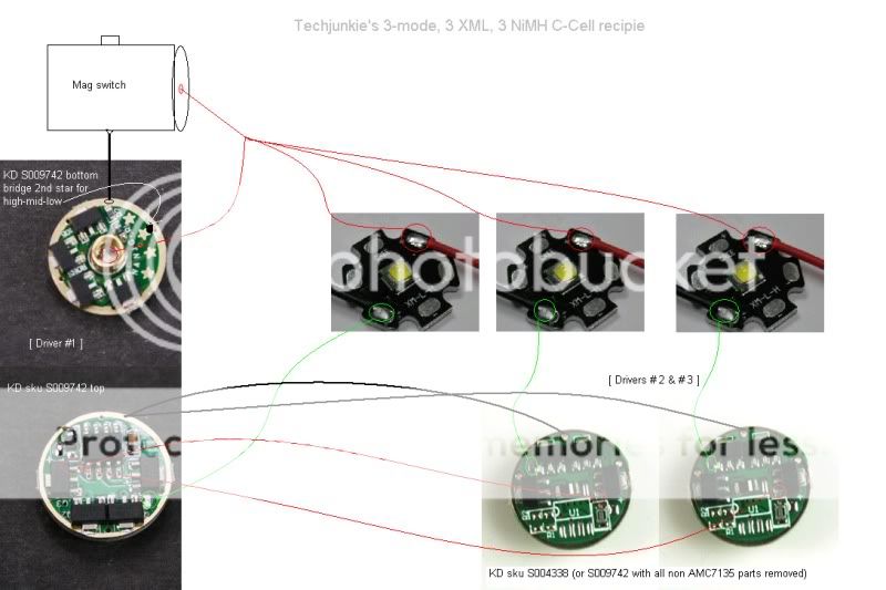
It appears that's not your fault though. You are only powering the main board (2.8A) if you have connected it like the schematic above.
Thats because I think the schematic is incomplete
If I'm wrong I'll edit this post, because it will only confuse people :x.
Epsilon, the schematic isn't incomplete in the way you described. That's how to wire this setup, but with one small but important correction, I forgot to draw the ground wires on the last two, the way I had described in post #7 above, "heavy copper wire was used on the outside edges of them"
Contrary to what you suggested, if you were to power the 2nd and 3rd directly, the VDD would have no mode effect because the 7135s would always be at full blast. Think of the VDD as the power source for all the 7135 chips. When it's on, they're on. When it's off, they're off. The controller chip powers that VDD lead on and off rapidly to create the PWM modes. Full blast is constant on and the lower power modes are just very rapid on-off cycles.
I'll edit the photo to include the ground wires to avoid further confusion.
Sorry Rich!
Last edited:
 :whoopin:The SST-90 and a rebel reflector are a nice combination. Good Work!