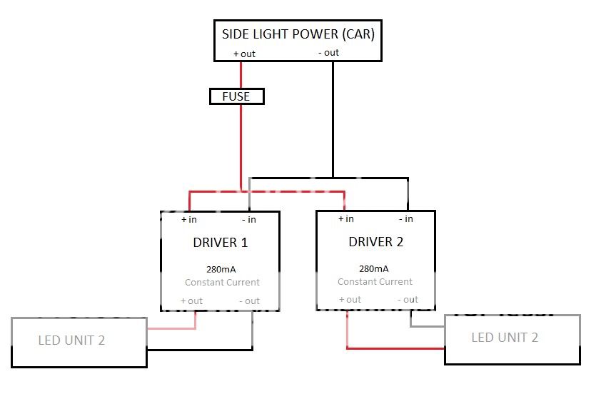
I have a slight problem, when testing the Driver and LED with a spare car battery it all works fine but when actually connecting to the side light powe source of the car, the driver blows a fuse and if i change the fuse to higher amps, the driver just shuts off. any ideas why this could be happening? i tried with another driver that is very similar and the other driver works fine but the diffrence is that the other driver has a 12V regulator soldered on to the input wire.
The supplier of the driver recommends I use a 5W 12V or 13V Zener Diode to keep the voltage at 12V. He thinks that the high voltage is causing the driver to draw too much current. I just dont understand how a 280mA constant current output driver is blowing a 2A fuse, because i measured the current draw from the driver to the LED and it's 280mA exactly. And even when i increase the fuse size, it doesnt blow the higher rated fuse but instead the driver shuts down.
any help would be very much appreciated.
thanks
Last edited: