Ferei W150

Doc Ed

Newly Enlightened
Joined
Oct 20, 2010
Messages
53
Location
Manila, Philippines
Bringing back this thread because I've got a renewed interest in this light. My current primary light is a modified bicycle light, and I was thinking of converting this "proper" dive light into a sturdier version that what I'm currently using.

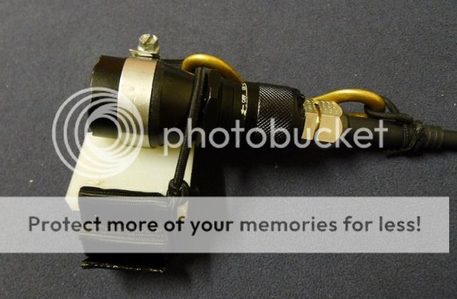
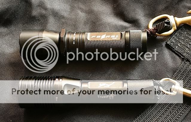
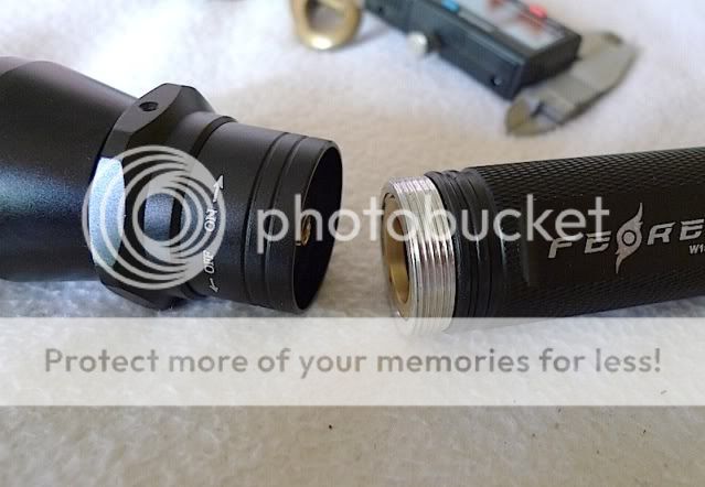
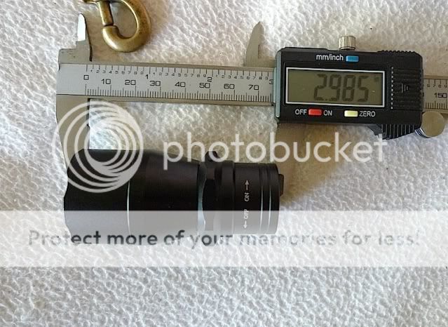
As mentioned previously, the construction of the light itself is rather good. Here's a side-by-side with my current back-up, a Trustfire TR-J1:

IMG_0805.jpg


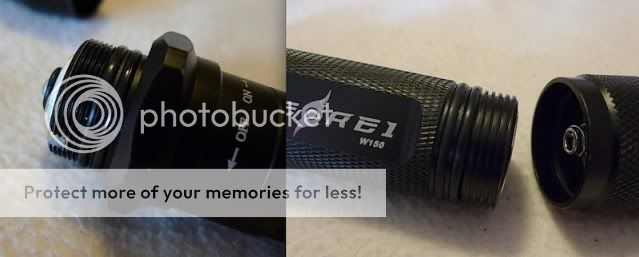
The battery tube and switch assembly of the light can be easily removed from the head. At the tail cap are some square cut threads, and both ends are protected by double O-rings.

squarecut.jpg


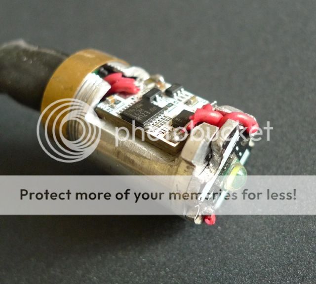
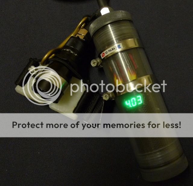
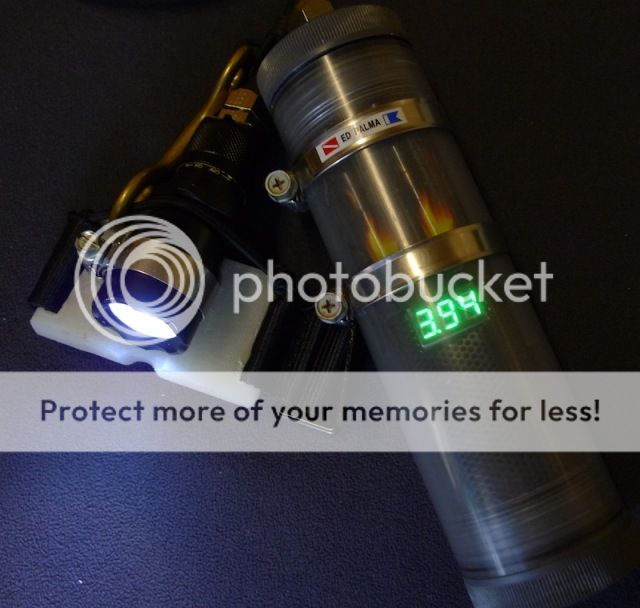
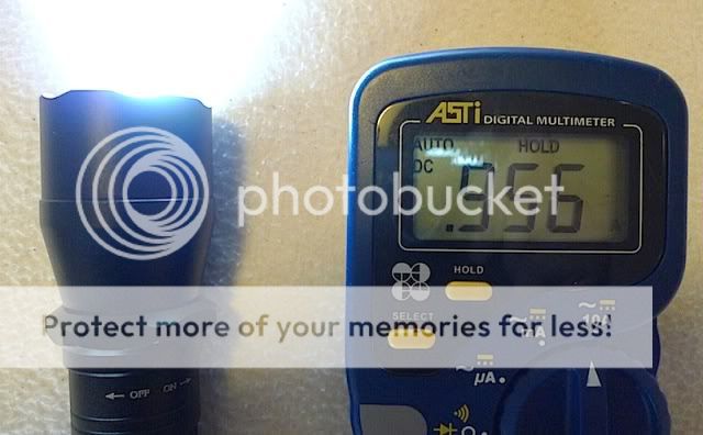
The "light engine" as mentioned by Arek98 seems to feature 3 7135 chips (not too sure on this though), giving about almost 1A of current at the tailcap (single 18650 around 4.01v only though)

driver.jpg


P1020573.jpg


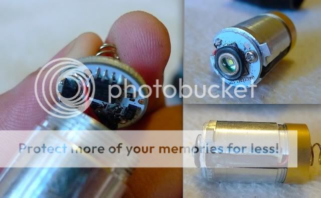
The magnetic switch can be disconnected from the rest of the battery tube. This is what I intend to do when I convert the head to an XML for can-light purposes:

P1020590.jpg


P1020593.jpg


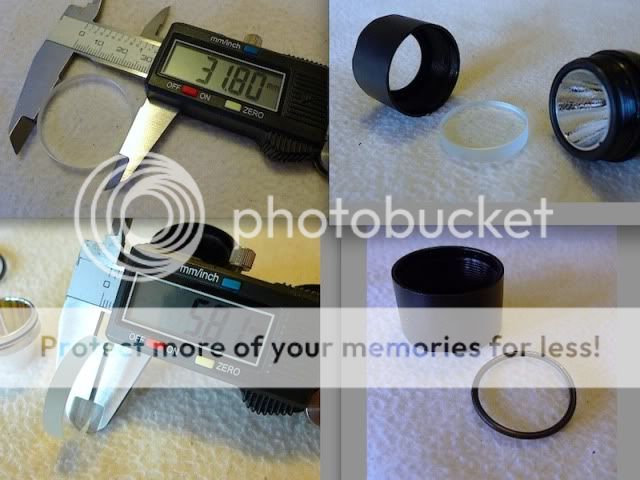
The head itself is pretty robust. There are several O rings on the front part alone: In front of the lens, behind the lens, around the edge of the reflector, the base of the bezel, and even around the base of the emitter.

reflectorandorings.jpg


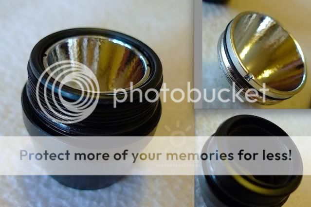
Considering its diameter, I think the lens is more than adequate to do its job :D

lens.jpg


So here's my question now: I purchased some proper Agro cable glands courtesy of 350xfire, and some proper cable as well. Likewise ordered a latching hallswitch made by Taskled. I was thinking of enlarging the space in the "light engine" and slipping in the switch over there so the original magnet can still actuate the light. Also got some 8x7135 drivers to drive the XML I have to almost 3A. Considering the dimensions of all of the above, and with the caveat that this light will definitely be only for underwater use, do I have to worry about overheating the components with these specs?
 
Last edited:

arek98

Enlightened
Joined
Dec 21, 2006
Messages
424
Location
New Jersey, USA
Ed, you will easily cool one XM-L underwater.
Instead of 8 AMC drivers and hallswitch I would try to fit LFlex inside. It is 19.8mm diameter but without batteries and needed contact you can play with heatsink and probably make it fit.
With LFlex you can use reed switch to control it (original one or molded version for extra ruggedness), it may be tricky with rotating ring but probably doable (and only programming is hard, you could use external magnet for it if needed). With LFlex you get levels control, thermal protection and battery protection.

Remember that for one XM-L and either AMC or LFlex you should use only one Li-Ion as power source (of course you can connect couple cells in parallel).
 
Last edited:

Doc Ed

Newly Enlightened
Joined
Oct 20, 2010
Messages
53
Location
Manila, Philippines
Thanks for the reassurance re the cooling :D I figured if it was only used in water, that it would pretty much survive. My current pack is all in parallel, so voltage is 4.2v. Considering that the driver and switch are already en route from 350, I'll try doing that mod first. I'm actually only after one mode, or at most 2 to conserve power, and the KD driver I got can be programmed to do Hi and Med via current modulation and not PWM, so there won't be any problems when taking video.
 

Doc Ed

Newly Enlightened
Joined
Oct 20, 2010
Messages
53
Location
Manila, Philippines
Finally finished my mods to the W150. After getting the parts from Hector, I managed to cobble together the W150 into a compact light head. I had to modify the pill to accept the taskled hall toggle switch, but with some creative wiring, I was able to fit the KD 3A driver (programmed for 2 hi-med), the switch and an XML star. The original magnet still actuates the switch.

P1020723.jpg


The head is bigger and more robust than my previous ferei build:

P1020733.jpg


(I had plans to make a handle from some bits of aluminum, but ended up doing the lazy thing and cut up an old chopping board I had)

While I was modding the head, I decided to update my battery pack. I purchased some proper 18650 battery holders, as well as a digital LED voltmeter and the small USB CC/CV linear charger:

charger.jpg


At least now I'm able to remove the individual cells of the pack. The voltmeter is activated by a reed switch, so it isn't constantly on, but bringing a magnet close to it allows you to see the charge state of the pack. (here it is charging)

P1020726.jpg


The use of a clear canister (an idea from 350xfire) allows the charge state to be seen anytime even during a dive (as well as check for leaks :D ). This is with my old OMS canister. Though discontinued, I believe new ones are available from 350.

P1020743.jpg

P1020744.jpg
 
Last edited:

Doc Ed

Newly Enlightened
Joined
Oct 20, 2010
Messages
53
Location
Manila, Philippines
That charging "window" is totally cool!

Yeah, its great that I can see the state of charge of the light... or at least my buddies can, and then tell me what it is :D

canisterinaction.jpg


One quirk I've encountered with this set-up however is when I switch to medium mode - done by flicking the switch several times quickly to toggle the modes. On medium, sometimes the hall switch subsequently fails to react to the magnet, thus necessitating me to slightly unscrew the canister to switch off the light. If I just stay on "high" mode, there seems to be no issue with the switch. Any ideas? Personally, I'm quite content with just "high", but it bugs me that one mode has a quirk I can't figure out.
 

Doc Ed

Newly Enlightened
Joined
Oct 20, 2010
Messages
53
Location
Manila, Philippines
Spec sheet say its good from 3V to 25V. Actually, voltage sag is less in medium mode than in high mode, so its probably not that.
 

Doc Ed

Newly Enlightened
Joined
Oct 20, 2010
Messages
53
Location
Manila, Philippines
I've got a big magnet inside my canister as well (as back-up, and to actuate the reed of the LED). Tried moving the head near that. No effect. Its seems that on medium mode, the switch doesn't want to unlatch.

Here in this video, you can see what happens. Voltage starts out at 3.9 and sags to around 3.76 on high. Cycled twice on high - no problem. Was able to do one mode toggle to medium, but subsequently, the light refused to toggle off from medium (3.88v).


Tryger

Newly Enlightened
Joined
May 12, 2013
Messages
5
I'm owner of a Ferei W150 as backup diving torch, and it don't works. :mad:

The two wires of the magnetic switch are desoldered, has anybody info about where to solder it again??

img1367hb.jpg


Any help will be appreciated!!
 

DIWdiver

Flashlight Enthusiast
Joined
Jan 27, 2010
Messages
2,725
Location
Connecticut, USA
It doesn't look like they are unsoldered, it looks like they broke from being bent back and forth for some reason. There should be the remains of the wires still in the solder at the points where they originally attached, and you should be able to see them. A stranded wire broken at a solder point is a very distinct and unmistakable pattern. Usually.
 

Tryger

Newly Enlightened
Joined
May 12, 2013
Messages
5
It doesn't look like they are unsoldered, it looks like they broke from being bent back and forth for some reason. There should be the remains of the wires still in the solder at the points where they originally attached, and you should be able to see them. A stranded wire broken at a solder point is a very distinct and unmistakable pattern. Usually.

Thanks DIWdiver I have very little experience in electronics and can't see where the wires were attached. I have taken two macro pics with the SubSee lens, maybe can help.

p1060411.jpg


p1060409ls.jpg
 

DIWdiver

Flashlight Enthusiast
Joined
Jan 27, 2010
Messages
2,725
Location
Connecticut, USA
Well, one point is clear as day, on the right hand side of the small black component just to the right of the two "K" shaped symbols in the upper picture. I can even make out strands of wire left there.

The other point though, eludes me. It could be the very uppermost feature in the first picture, or the mess between the two diode ("K") symbols, or maybe something else.

Perhaps some other kindly F150 owner will post a pic.
 

lucca brassi

Enlightened
Joined
Feb 1, 2008
Messages
889
Location
US
probably not . I have just looked this combination PIC12F629& AMC 71350 and it is similar to yours . Picture is not so good to made some conclusions.
 

Latest posts

Top