
ti-force
Flashlight Enthusiast
Cool stack but since 1xIMR26650 is not going to be able drive SST-90 to 9Amp even in Direct Drive,
there's really no need for a buck driver in such application.
All you need is a PWM to control modes like d2flex.
I'm actually trying to figure out a good way to run both of my IMR26650's in parallel. I'm hoping that both of those batteries in parallel will supply 9+ Amps. I have some 1", shedule 40 PVC pipe that I cut to length and use to make up the additional inside diameter of the D sized mag body, (for when I use these smaller diameter batteries) and I'm thinking that I can make a parallel battery holder out of it. Any ideas?

Last edited:

 . Don't ask me how I know
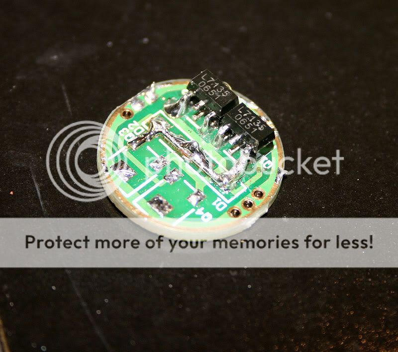
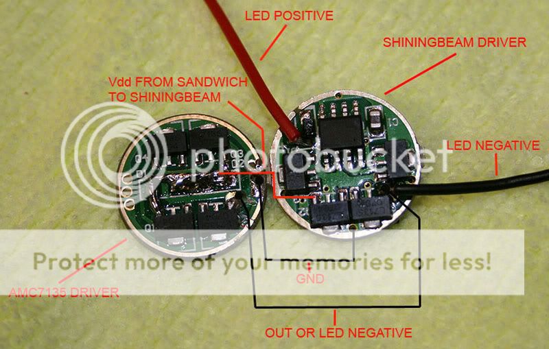
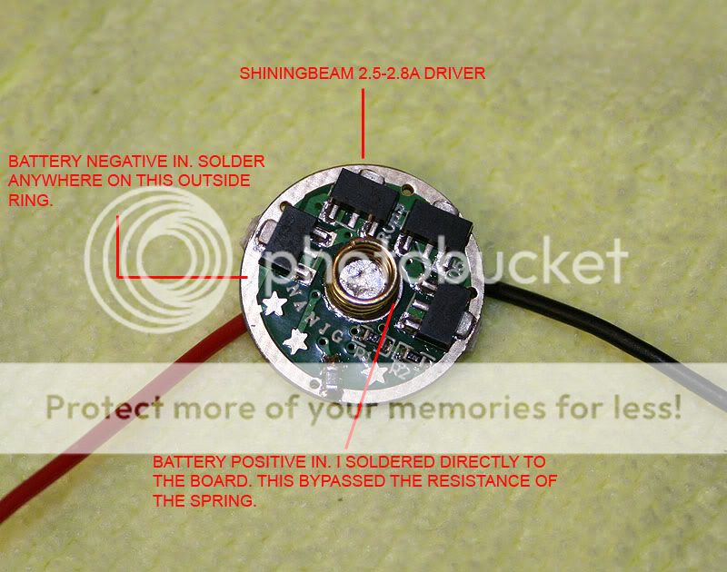
 . You could not possible even know how much this helps me. I have been beating myself to death trying to truly understand the current path for this type of driver. I was assuming one very fatal thing. I thought that the center leg was the ground or bat neg in, and that BOTH of the pins on the left and right were NEG OUT. So you can imagine what a :toilet: time I have been having trying to figure this out
 . That has got to be the most valuable nugget I have found on this driver in a year. I have been able to use these drivers a lot, but I prefer to truly understand what I am doing rather than just copying.