Squeezing the power out of a Supercap

jdp298

Newly Enlightened
Joined
Mar 22, 2011
Messages
115
Location
With your sister, somewhere you wouldn't like
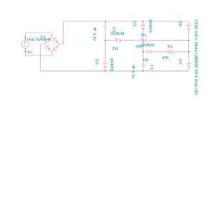
Tell you what Simon, that's a decent enough and pleasingly simple circuit. Glad it works.

After all that time examining the ZXSC310, I went with a copy of what I did before. I got another old style light off ebay 99p plus p+p; it's aerodynamic, but only from behind, and there's really not the space for a large circuit inside. The only variation is that I went with 5v LDOs and 3x 13ohm 0.5W resistors in parallel to give me 4.3ohms at over 1 Watt. Bit of an experiment to see if it either lasts longer or shines brighter on standlight. Initial results indicate neither, whaddya know? And there's a switch.

The end result, tested in the park just this evening, is ideal. I think it's bright enough to ride any tarmac road regardless of ambient lighting. Photos to follow. The previous B&M halogen senso sucked the life out of the LED before and was a bit too warm a white. For anyone interested, it'll be on ebay itself some time over the weekend.
 

SimonInd

Newly Enlightened
Joined
Oct 19, 2011
Messages
20
No idea on the manufacturer Steve, it's a coin cell form factor with just 4.0F 5.5v marked on it. Here's a link to the eBay listing (I am in no way connected to the seller) but this says nothing about who actually makes the cap.
http://www.ebay.co.uk/itm/4-Farad-S...284?pt=LH_DefaultDomain_0&hash=item3cbdb1515c

Googling seems to just bring up chinese wholesalers on alibaba.com rather than the actual manufacturer so I've no idea of the ESR etc.

The diameter is a bit of a pain as I was originally hoping to squirrel them away inside a torch that takes a 18650 cell, however they are cheap for their capacity and the 5.5v rating helps keep the circuit simple.

Having given this a bit more thought, I don't think there's any reason why I can't make the circuit more symetrical and charge the supercap for the rear light up to 5.5v as well, perhaps some more experimentation this weekend...

Cheers
Simon
 

krienert

Newly Enlightened
Joined
Mar 15, 2010
Messages
38
wow. Ive got some motivation to seek supercaps in the order of a dynamo circuit.

I have two 2.7v 150farad caps... but am really concerned about being able to charge them reasonable on the cycle from dynamos.
Any ideas that trek in stride with the other posts thus far?
 

steveo_mcg

Newly Enlightened
Joined
Jan 18, 2010
Messages
74
Location
Edinburgh
They'll take a few minutes to charge by dynamo, for me though the size would stop me from using them on a light build.
 

jdp298

Newly Enlightened
Joined
Mar 22, 2011
Messages
115
Location
With your sister, somewhere you wouldn't like
Yeah, they're pretty massive. Some simple numbers: Energy on capacitor at full charge = CV^2 = 150*2.7^2 = 1093Joules per cap = 2186J
Energy from a dynamo providing 7v at 0.5A = VAt rearrange for t = 1093/7*0.5 = 312s, or just over 5 minutes, assuming 100% charging efficiency. In reality it's about 60 to 70% so more like 6 or 7 mins. With 2 caps, suddenly you're at 12 or 13 mins. Have a long commute do we?

I run two 1 Farad caps at 5.5v for each of 2 front lights and another single cap at the back. = ~90J. Lights come up in about 2 seconds and full brightness once stopped after 20s or so. The nice thing about the LDOs I use is that they fade the 1W front LEDs quite quickly from full on but keep going as pretty reasonable lights to be seen by for a good 5 mins. The rear LED, just being a superbright red, stays full brightness for 3 or 4 mins and then fades gradually, but it takes a lot less current and so only needs 1 cap.
 

MikeAusC

Enlightened
Joined
Jul 8, 2010
Messages
995
Location
Sydney, Australia
wow. Ive got some motivation to seek supercaps in the order of a dynamo circuit.

I have two 2.7v 150farad caps... but am really concerned about being able to charge them reasonable on the cycle from dynamos.
Any ideas that trek in stride with the other posts thus far?

How about a circuit which feeds most of the Generator current to the LEDs so you get some light instantly, and any surplus current charges the supercaps.

Keep in mind that when you put two supercaps in series, you MUST have a balancing circuit to ensure that neither capacitor goes over its voltage limit.
 

krienert

Newly Enlightened
Joined
Mar 15, 2010
Messages
38
I am starting to see that the 150 farad caps are a little over kill for only a 10 mile trip (20 round trip). I average about 20mph so its really only a 30 min trek.
If anyone wants one of these I might be inclined to share if someone can be of help in working out a working standlite circuit.

Maybe I should start a new thread though... as this might be diverging from this post.

Heres a hook thou...
I have some of the mentioned 5.5 volt 1 farad caps-sounds like these will work much better. Although I have tryed a couple circuits, im having a rough time getting
them to charge and power my test 'lamp'. Actually, I never got the leds to lite even after a moderate pace on the workbench (floor w/bike upside down) for about 1
and a half minuits. At which point, I stop - so to not over load the cap. Yet when I short the tabs, there is no visable spark - showing no charge at all is getting through.

The setup is a 0-10vdc 500mah output (magnetically rotated stepper motor) through a shokty bridge, then to the leads on the cap and to a small array (x9) 5mm cool white leds.
Mearly a test setup right now, and I still cant get the diodes to illuminate with the supercap. It works fine with 3700uf 50v but the leds dont hold enough to be 'stand' lites.

Should I go ahead and bump this to another post?
 

krienert

Newly Enlightened
Joined
Mar 15, 2010
Messages
38
not quite.
just a small test rig. It could sure run 12 v, but would be pushing it.
Its actually the small board from one o thos cheapy $2 aluminum
lights from the junk box. It has 9 leds (1 center-8 outer) ran in parrallel not series... if that helps?
(originaly powered by a x3-AAA block)
 
Last edited:

jdp298

Newly Enlightened
Joined
Mar 22, 2011
Messages
115
Location
With your sister, somewhere you wouldn't like
There are quite a few standlight circuits cutting around these parts. Mine's pretty simple but lacks absolute efficiency and brightness, while Steve K's is the platinum plated solution but quite a bigger build. Diagram of mine here:
http://www.flickr.com/photos/jdp298/sets/72157626884852454/


What's the normal current draw and voltage requirement of the white LEDs? If 3 AAAs do it, then that's about 4.5v. If you can find a 5v Low Drop-out Regulator, then put a series resistor, knowing the current, before the LEDs, then that ought to work. I protect the front lights' supercaps with a zener diode, but that's really for paranoia's sake, I don't use one at all in the rear light.
 

krienert

Newly Enlightened
Joined
Mar 15, 2010
Messages
38
thank you for that link. somehow I missed it.
I am going to rigg some parts together in the next few days and post what I come up with.

My offer still stands on the 150f 2.7v cap for someone whos a tinkerer in such sorts.
I am having trouble comming up with the adiquite componets to charge these - so a bargan buy is
only gathering dust at the moment.
If someone gets something to work with one, I would ask in trade the concept for one of em.

(if you had not already noticed, my electrical skills are intermediate)

Cheers and thanks
 

krienert

Newly Enlightened
Joined
Mar 15, 2010
Messages
38
woo hoo jdp. Your little diagram worked.
It took about 20 sec for the low mah of the dynamo to get enough charge into the capacitor to alow the leds to see the current.

I have a question, what keeps the cap from over charging?
 

jdp298

Newly Enlightened
Joined
Mar 22, 2011
Messages
115
Location
With your sister, somewhere you wouldn't like
The cap is dependant on the voltage you put across it. 2 easy ways. (1) After the rectifier, have a zener, as per my circuits. However, you might find that the 2.7v limit of those caps of yours is a little low to fire a powerful LED. (2) Have a voltage regulator, be it a LDO or say a LM317 (not so good for dynamo apps) and regulate the voltage to a safe level for the cap.

However, the ZXSC310 boost regulator circuit is probably the favourite to get the best out of your caps as it can take the 2.7v and boost it up to what you need for the LED. I think circuit minisystem uses, which is dead similar to Steve K's, is the guide here.

If you overcharge the cap too much, too strongly, then probably you will end up letting the magic smoke out, and that's bad. Without magic smoke, most electronic components won't work any more. Imagine how the circuit will behave once the cap is fully charged and nothing is going into it any more, what voltages would/could be generated? Or just run the circuit without the cap and measure what happens.
 

minisystem

Newly Enlightened
Joined
Jul 12, 2011
Messages
96
I went with the LDO route for charging the cap in mine (still a work in progress). SteveK wins the grand prize for awesomeness for discovering the ZXSC310 boost regulator. It's very easy to use and the datasheet says it all.

One thing that is an issue for me is regulating the current going into the supercapacitor. In my circuit, they suck up all the juice leaving none for the LEDs until they reach some minimum charge level. I used a current limiting load switch to keep the voracious jaws of the supercapacitor at bay as it charges, leaving enough current for the LEDs. Not being an EE I went with the simplest 'off the shelf' IC I could fine, although I'm sure a cheaper/simply discrete method is possible. All the details are here: http://minisystem.blogspot.com/2011/09/charging-supercapacitors.html
 

steveo_mcg

Newly Enlightened
Joined
Jan 18, 2010
Messages
74
Location
Edinburgh
That is standard behaviour for capacitors, when empty the behave almost as a dead short, once they start to charge their voltage rises and eventually their voltage will rise to a level that allows the LEDs to function. That's why most people put them in parallel. Would it be possible to run a seprate circuit to run one of lights and leave it with out a stand light?
 

jdp298

Newly Enlightened
Joined
Mar 22, 2011
Messages
115
Location
With your sister, somewhere you wouldn't like
Steveo

That's what Steve K does. His circuit runs up to 4 LEDs, but only 1 is powered as a standlight. Because they all come from the same power source, something like what minisystem has as a charging circuit is your best bet to limit the current 'lost' to charging the cap. Steve actually runs with a rechargeable battery for his power source. I get away with it because my caps aren't all that big and my LEDs not too crazy powerful, so at the end of it all I get light on quickly and 5 mins standlight plus a bit as it dims right down.
 

SimonInd

Newly Enlightened
Joined
Oct 19, 2011
Messages
20
So here's a quick update for anyone interested. I now have front and rear standlights operating nicely with only two supercaps and I don't think I'm wasting any of the dynamo's output once the caps are charged so I've got nice bright lights. I'm using the fact that the LEDs effectively clamp the dynamo output voltage at 6v (3.6v front XM-L and 2.4v rear XP-E) so a single 1N4001 can stop the 5.5v supercaps from seeing too much voltage. These discharge via 47R resistors to power the LEDs when the dynamo has stopped. The extra diodes, D4 and D5, prevent the capacitors from discharging through each other's LED.

I'm going to commute with these this week and see how they fare but the initial tests look very promising. The circuit fits inside a single chrome retro front light which makes it nice and neat. If the circuit works well then I'll see if I can improve the optics of this as it was originally designed for a bulb.

Cheers
Simon
dynamo%20with%20standlight.png
 

jdp298

Newly Enlightened
Joined
Mar 22, 2011
Messages
115
Location
With your sister, somewhere you wouldn't like
As I read it, when you're stopped, C1 will power the front light with no resistor, but also charge C2 and help run the rear light. There must be something going on here I don't get, why are D4 and R1 where they are? Does the front light fade quite quickly?
 

krienert

Newly Enlightened
Joined
Mar 15, 2010
Messages
38
ok. Here is a simple sketch of what I'm trying to solve.
I need advice on the s. cap protection and also the pre LED regulation.
FFJFEUEGV0RRK1T.jpg

Anyone know if my plans for the transformer make sense as well?
Got a feeling that it might not work as well as depicted due to the
lower ac voltage.

Do your worst - it surely needs it.

Cheers.
 

Steve K

Flashlight Enthusiast
Joined
Jun 10, 2002
Messages
2,786
Location
Peoria, IL
The red LEDs will clamp the output voltage. You just need to limit the current going to them.
One method would be to just add a resistor in series with the LEDs. Not efficient or precise, though.
2nd method: add another string of LEDs in parallel with the first in order to handle the 750mA from the transformer.
3rd method: reduce C1 and C2.
4th method: change the step-down ratio of the transformer so the output current is less.
5th method: skip the transformer. Full wave rectify the output of the solenoids, filter it, and then feed it into the input of a current regulated buck converter.

So what's the story on the solenoids and the "rotating magnetic platter"?

regards,
Steve K.
 
Top