Squeezing the power out of a Supercap

krienert

Newly Enlightened
Joined
Mar 15, 2010
Messages
38
Steve,
Thanks for the clear feedback.
>I gave a try at winding my own transformer last night-and didn't have much success. So your notion to full-wave the AC output might be the best method.
>As far as filtering is concerned: Do you mean adjust the smoothing caps prior to the bridge (smaller value),  and adding a shockty pre s. caps?
>I found something last night that might be an option.
-I could full-wave, filter, then maybe get one of the many lux buck drivers as you advised.
-or, I could possibly get the lux driver that is ac/dc, something called a bullet?
I would maybe need to ramp my AC voltage prior though, as the needed baseline voltage is 5vac (max. 35vac).

>The platter? well... without being complicated, it's just like an axial wind turbine setup but rather than a twin rotor, it's a single. And rather than wind, it is my bicycle drive train. Currently setup at 1x1 : 56crank-14drive.
-At 60rpm pedaling, I get about 240 on the cog. Behind the cog, is a steel plate with a circumference axial magnet array.
-It's made of recycled parts, and has a really good output for no magnetic or mechanical friction.
-The number of alternating poles on the platter facing the solenoid is 8, so...
>240rpm=1900hz and 400rpm=3200hz.
>The two solenoids are wired in series with spacing over the magnets that equals both receiving flux simultaneously (or as one coil).
My math isn't exactly pro - but rough estimates are better than none.
hope at least some of that made sence... If I can get a camera, maybe this would make more sence.
Its my poor mans option to not yet having enough $ for a dynamo hub.
cheers!
 
Last edited:

Steve K

Flashlight Enthusiast
Joined
Jun 10, 2002
Messages
2,786
Location
Peoria, IL
>As far as filtering is concerned: Do you mean adjust the smoothing caps prior to the bridge (smaller value),* and adding a shockty pre s. caps?
>I found something last night that might be an option.
-I could full-wave, filter, then maybe get one of the many lux buck drivers as you advised.
-or, I could possibly get the lux driver that is ac/dc, something called a bullet?
I would maybe need to ramp my AC voltage prior though, as the needed baseline voltage is 5vac (max. 35vac).

The filtering after the full wave rectifier is just intended to reduce the ripple to something that the buck converter can handle. There shouldn't be any need for other rectifiers. It may be helpful to put a zener diode at the input to the buck converter to make sure that the voltage doesn't get high enough to harm the converter.


>The platter? well... without being complicated, it's just like an axial wind turbine setup but rather than a twin rotor, it's a single. And rather than wind, it is my bicycle drive train. Currently setup at 1x1 : 56crank-14drive.
-At 60rpm pedaling, I get about 240 on the cog. Behind the cog, is a steel plate with a circumference axial magnet array.
-It's made of recycled parts, and has a really good output for no magnetic or mechanical friction.
-The number of alternating poles on the platter facing the solenoid is 8, so...
>240rpm=1900hz and 400rpm=3200hz.
>The two solenoids are wired in series with spacing over the magnets that equals both receiving flux simultaneously (or as one coil).
My math isn't exactly pro - but rough estimates are better than none.
hope at least some of that made sence... If I can get a camera, maybe this would make more sence.
Its my poor mans option to not yet having enough $ for a dynamo hub.
cheers!

Interesting! Pictures would be handy.
I can see where it would be fun to build one, but the difficulty of optimizing the magnets, the windings, the magnetic flux path, etc., is significant. If it does what you need it to do, though, then it's good enough! :)

regards,
Steve K.
 

steveo_mcg

Newly Enlightened
Joined
Jan 18, 2010
Messages
74
Location
Edinburgh
>The platter? well... without being complicated, it's just like an axial wind turbine setup but rather than a twin rotor, it's a single. And rather than wind, it is my bicycle drive train. Currently setup at 1x1 : 56crank-14drive.
-At 60rpm pedaling, I get about 240 on the cog. Behind the cog, is a steel plate with a circumference axial magnet array.
-It's made of recycled parts, and has a really good output for no magnetic or mechanical friction.
-The number of alternating poles on the platter facing the solenoid is 8, so...
>240rpm=1900hz and 400rpm=3200hz.
>The two solenoids are wired in series with spacing over the magnets that equals both receiving flux simultaneously (or as one coil).
My math isn't exactly pro - but rough estimates are better than none.
hope at least some of that made sence... If I can get a camera, maybe this would make more sence.
Its my poor mans option to not yet having enough $ for a dynamo hub.
cheers!

Ooh, thats interesting! I had thought about converting a rear disk brake into a really high power EM brake using a similar technique. It would probably need bigger coils thought to really suck the energy out.
 

Steve K

Flashlight Enthusiast
Joined
Jun 10, 2002
Messages
2,786
Location
Peoria, IL
This may have been discussed elsewhere, but making this sort of dynamo has some inherent inefficiencies. Primarily, you would need to have coils around the entire circumference of the disk in order to be able to utilize all of the magnets all of the time (as is done in a hub dynamo). This would present issues with being able to remove the wheel, of course.

Another inefficiency is the extreme difficulty in maintaining a small gap between the disc and the windings. The smaller the gap is, the greater the magnetic flux, and the greater the dynamo output. Pull apart any cheap DC motor and look at how close the rotor gets to the stator. That's probably the gap size that a dynamo should be. Probably under a mm, I'd guess. Part of the problem is the ability to keep the disc flat/true/straight. The other part is the ability to accurately position the wheel in the frame.

I'm not trying to rain on anyone's parade, but anyone experimenting with this sort of gadget should know that there are some intrinsic limitations. A spoke dynamo might a better solution to the problem of an affordable, efficient dynamo (but there are issues with these too...)

regards,
Steve K.
 

krienert

Newly Enlightened
Joined
Mar 15, 2010
Messages
38
Side
FGKTNI8GV1HFIGN.MEDIUM.jpg


top/bottom
FQ1GDNMGV1HFIGJ.MEDIUM.jpg


Not exactly a high-end professional setup - but it works dang well.
Considering its made from 85% recycled parts - and outputs 21Vac (150mah) at 90 pedal rpm, I am satisfied.

The air gap between the platter and the solenoids is 1mm + .5mm on each surface of rubber coating=2mm total between flux and cores.

It seems that with some braceing-adding a 3/4 circumfrence ring will be no problem. Something like 3 pairs (6 total) coils to wire in 3-phase maybe?

I started making a couple more, and want to share... but not before I get this filtering and lighting circuit figured out.

Any corrections?

added: I also tried working with spoke mounted magnets, yet I found that centering them to the hub simplifys having a level true surface to work on the possitioning of the solenoids.
Unfortunatly one drawback to this is that there is significatly less circumfrence to provide the alternating poles. For safetys sake, I was cetching metalic road debrie with the spoke mounted
magnets - and this opted me to try and keep the flux as far away from the tarmak as possible.

added again!: I just realized looking at these photos, that the solenoids look like little black gummy bears!
 
Last edited:

jdp298

Newly Enlightened
Joined
Mar 22, 2011
Messages
115
Location
With your sister, somewhere you wouldn't like
A dynohub isn't that much. I have a Shimano Dh-3N30, cost £25 from a shop in Oxford. Spokes another £19 and I built the wheel with the old rim, tyre, inner tube etc in the front room with no more than a spoke key and a screwdriver. Bit of time to true it once on the forks but you can do that by eye and feel and 1300 miles later we're still doing fine. Compare that to a fancy light and it's peanuts. Even an old Sturmey-Archer hub rated at 1.6W will run my circuit with a front and rear standlight, and you can get all of the above off Ebay. Except the spokes, I'd say get some new spokes. Go on, treat yourself.
 

krienert

Newly Enlightened
Joined
Mar 15, 2010
Messages
38
jdp,
are you egging me on when I am trying to keep a budget? ;)
Advice noted, and the demensions of the Sh-dh80 center to spoke hole measurements match the hub I already have-so the turnover would be easy.
In the mean time, this really seems like a possible setup. At least maybe for a pair in the back?

Then possibly a front hub dedicated to the front light only?
 
Last edited:

pantaz

Newly Enlightened
Joined
Oct 19, 2011
Messages
9
It seems that with some braceing-adding a 3/4 circumfrence ring will be no problem. Something like 3 pairs (6 total) coils to wire in 3-phase maybe?
It looks like you have room for it. There are quite a few good plans for wind turbines that might be helpful in working out the specs for the coils. For example, http://www.instructables.com/id/DIY-1000-watt-wind-turbine and http://practicalaction.org/docs/energy/pmg_manual.pdf.

I would also lose the transformer. There's really no need for it -- a simple voltage regulator should serve your needs.
 

krienert

Newly Enlightened
Joined
Mar 15, 2010
Messages
38
wow. those articals were great. Thanks man.
everybodys tips motivated me adding a 3rd coil from my parts bin this morning.
Alot more gusto.
Now I just have to figure out the supercap circuit. Probably will have to start from scratch now that I have the 3rd coil and its true 3-phase instead of two phase.

Once I get these three coils in conjunction-can I just directly bridge their dcV with another small wheel dyno I have for one soild rear power source?
Meaning... (3coils>0-20DCv@150mah) + (dynamo>0-15DCv@150mah) = ?A smoother dc source prior to filtering with combined mah max. rating of 300mah?
:confused:
If you dont mind, heed understanding in my novice electrical skills.

cheers.
 
Last edited:

jdp298

Newly Enlightened
Joined
Mar 22, 2011
Messages
115
Location
With your sister, somewhere you wouldn't like
Your power output will determine what LEDs you can run. 20v at 150mA is 3 Watts (20 x 0.15). That's the same power output, give or take, as a properly expensive SON hub dyno. I run a 1W white LED at the front and a super-bright red at the rear. Together they draw no more than 1.2W. So I made another front light, 2.3W all in. All 3 lights are run by the 1 hub dynamo, I just route a pair of wires from fwd to aft, couple of cable-ties and we're away.

Once you rectify any AC, you get a kind of mountain range of dc pulses all together. To smooth those out to a flat dc voltage, normally you put a capacitor across the positive and negative terminals of the rectifier. At the risk of repeating myself, I posted the link to my circuit at the end of page one of this thread. The supercaps act as the energy reservoir but also as the smoothing caps.

I could use a normal voltage regulator, but the problems come when you stop. For example, if I regulate to 4v, then when the supply drops to less than 4.5v (say), I get nothing out of the regulator. This means that the capacitors, holding 5.5v on them, still have 4.5v but can't use it. This is why I went the LDO, or Low Dropout Regulator, route. Correcting what I said inaccurately the last time:

If the LDO regulates to 3.3v (a common value), then any supply above 3.3v will result in that coming out of the regulator. When the supply drops below the normal output, it still passes what voltage it can, at something like 80-90% efficiency, until the supply reaches only 20mV in some cases. This means you get to use a lot more of the energy stored on the supercaps when you stop and means the light coming out the LED gradually fades away.

As a circuit, it's simple and effective. It's not sophisticated, but if you look at the pictures I linked to on my Flickr account, you can cram it into some pretty small spaces with something as backward as vero-board. Each light on my bike has a separate rectifier, essentially they all run in parallel to each other so the failure of 1 will probably not result in the failure of the others.

Finally, you need to know the normal forward voltage and current of the LEDs you want to use. The 1W LEDs I use are rated at 350mA, 3.2 to 3.5volts. So I use a 3.3v LDO regulator and no resistor. The output voltage can't run away because it's regulated. The rear red LED has the same 3.3v regulator but is rated to run at 2.2v, 50mA. The calculation for what resistor you now want goes like this: (Output volts-LED volts) divided by (LED current) = (3.3-2.2)/0.05 = 22 ohms. That value resistor goes in series with the red LED. I think you could run my circuits with what you've made.
 

krienert

Newly Enlightened
Joined
Mar 15, 2010
Messages
38
pulled due to detouring from the post title and bad artwork.
:sssh:
 
Last edited:

Steve K

Flashlight Enthusiast
Joined
Jun 10, 2002
Messages
2,786
Location
Peoria, IL
I think you need to edit the drawing a bit. The bottom phase should connect to the junction between the two diodes on the right instead of connecting to the anode of the lower diode. I'm assuming that this is just a typo or drawing error.

regards,
Steve K.
 

krienert

Newly Enlightened
Joined
Mar 15, 2010
Messages
38
your right. Drawing mistake. Thanks for the note Steve. I redrew it, and started another post, as I don't want to stray from this interesting topic of super-capacitor powering. I imagine once I get the starting bits sorted out, I will keep posting here, but until then - I felt bad about the distractions.

Cheers all on the info discussed so far. My bad Jdp.
 
Last edited:

SimonInd

Newly Enlightened
Joined
Oct 19, 2011
Messages
20
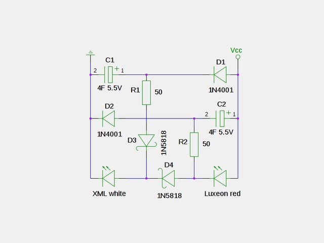
As I read it, when you're stopped, C1 will power the front light with no resistor, but also charge C2 and help run the rear light. There must be something going on here I don't get, why are D4 and R1 where they are? Does the front light fade quite quickly?

If you look at the circuit the charging networks built around C1 and C2 are identical, the only difference is whether the cap and LED are connected to +V or 0v. R1 and R2 stop the caps discharging too quickly and allow the voltage across the cap to be greater than across the LED it will discharge through. D4 and D5 are to prevent the cross charging of the capacitors, i.e. to ensure that C1 discharges through the front LED (via D4 and R1) only and C2 discharges through the rear.

I've commuted three times this week (28 miles round trip) and they seem to be working well, both last over 5 minutes, but the rear does last longer.

Cheers
Simon
 

jdp298

Newly Enlightened
Joined
Mar 22, 2011
Messages
115
Location
With your sister, somewhere you wouldn't like
Simon
I think I get where you've gone with this. However, what would happen if you removed the front LED from that cct? In effect, any charge on C1 would get through D2 into (the other) C1. I'd be tempted to simplify the circuit and have both capacitors in parallel, running both LEDs in series. This way you know how long the rear one lasts by looking at the front one. Plus you'd use less normal diodes and suffer less voltage drops across them. There's always another way with good old fashioned analogue stuff: - Whoever made an integrator from an op-amp and a capacitor was a genius.
 

SimonInd

Newly Enlightened
Joined
Oct 19, 2011
Messages
20
The problem with the LEDs in series is that the voltage across the combination is greater than the 5.5v rating for the supercaps. Even putting the caps in series to double the rating, ideally I want to be storing > LED's Vfwd in the capacitors to have decent run time when I'm stopped. My aim with the above circuit was to have all the power going through the LEDs when I'm on the move to get the brightest lights. This is why I have nothing else with voltage across it. Once the caps are charged everything should flow through the LEDs.
 

ejoyu

Newly Enlightened
Joined
Nov 20, 2011
Messages
5
Evening all!

I've been devouring all the dynamo related threads for the last month or so - some super interesting information in this forum!

I've just finished building my simple front and rear dynamo powered bike lights, and with the help of SimonInd's schematic in post #37 (link) have managed to ensure that the LED's remain lit when I've come to a stop. My schematic is below (note that the dynamo and bridge rectifier haven't been shown).

u0kOCl.png


The main difference between mine and SimonInd's is my D4 (equivalent to SimonInd's D4 in #37). I found that the schematic in #37 actually didn't work correctly for me - only my front Cree XML would remain lit (note my LED's are the opposite way round to SimonInd's), whilst the Luxeon extinguished as soon as I stopped. I'm a mechanical engineer by trade, so not too hot on the old electronics, but I figured that the position of D4 in the schematic in #37 must have been a mistake - surely it blocks any current from capacitor C1 from reaching the Cree XML? Well, it sort of made sense in my head, so I moved it. In its new position it still ensures capacitor C1 does not discharge into capacitor C2. D3 still ensures cap C2 doesn't discharge into C1.

I've gone up and down the street a couple of times, and it all seems to work fine. I have a question though - I'm using the same caps as SimonInd, and am worried: they could theoretically charge up to 5.5V (I presume, right?), but won't this be too high for each LED? Or does this just mean I need to allow for better heatsinking?
 
Last edited:

jdp298

Newly Enlightened
Joined
Mar 22, 2011
Messages
115
Location
With your sister, somewhere you wouldn't like
If I knew what the forward voltage of your LEDs was, we could work it out. Start by assuming the caps are fully charged, 5.5v on each. R1 will limit the voltage and current going through the white LED. C2 will discharge across the red, D4, and then the white, as well as through R2. If you want to work out what R1 and R2 should be, it goes like this:

(Capvolts-LEDvolts)/LEDcurrent = Resistor. Take Capvolts=5.5, LEDvolts and LEDcurrent from data sheet. R1 and R2 may end up different.

Actually the greatest risks I see here are: 1) that you might be shunting current through R2 as the path of least resistance when moving, rather than through both LEDs (therefore possibly causing the white one to be a bit dimmer than necessary). (2) That you might overcharge C2 and C1. For (2), you might want to consider a Zener diode across Vcc and Gnd. As the 1N4001 diode causes a drop of a volt or so, plus the natural tolerances of the caps, you could probably use a 6.2v to 6.8v zener, it depends on what your supplier has. This kind of wrangling is why I have a spearate rectifier and circuit for each light. More components but conceptually easier on the head.

Spot on with shifting D4.
 

ejoyu

Newly Enlightened
Joined
Nov 20, 2011
Messages
5
Thanks for replying! Yeah, I left out a bit of info in the post. Here's what I've got:

Front LED
LED: Cree XM-L T6
Colour: cool white
Datasheet: link
Current: 500mA (limited by output of bottle dynamo)
Vf @ 500mA: 2.8V

Rear LED
LED: Luxeon Lumiled 1W red (from eBay)
Colour: red
Datasheet: actual LED code is unknown, so no datasheet
Current: 500mA (limited by output of bottle dynamo)
Vf @ 500mA: 2.85V (measured on bench-top power-supply)

Each capacitor should charge up to Vcap = (2.8 + 2.85) - 1.0 = 4.65V (Vf of each LED, minus the drop across the 1N4001 diode).

So, using the standard V=IR:
Front: R = (Vcap - Vled) / I = (4.65 - 2.8) / 0.5 = 3.7 ohms
Rear: R = (Vcap - Vled) / I = (4.65 - 2.85) / 0.5 = 3.6 ohms

This seems to suggest that at full capacitance, the caps won't wreck the LEDs. I've done it the other way round too:
I = Vcap / R = 4.65 / 50 = 93mA <-- This is much less than the LEDs rating. The XM-L's can handle up to 3A!!

Hopefully I'm doing these calcs the right way round, and if so they do seem to suggest that on the "blowing-up" scale of things I've got nothing to worry about. If anything, I should probably swap over the 1N4001 for some Schottky diodes, as I've got a bit of room to spare.

As for shunting through R2 - yep, I can totally see that now. Not gonna lie - no idea what to do about that!

I commuted home with this setup tonight, and it seemed to work well. At least, I didn't start any fires! I did notice that the front LED seemed a little dimmer than usual (which would corroborate the R2 shunting) but it's tricky to tell from the back of the handlebars!
 

wednesday

Newly Enlightened
Joined
Nov 21, 2011
Messages
7
Hi everyone,

I've been following this thread and the standlight one for ages now, and trying to work things out between bouts of tears and despair prompted by the unending confusingness of it all. My main concern with a standlight is that it is highly visible (like a fool I ride on big roads on the bad side of town) and the attempts I have made to build one (that have worked) have been too dim to replace my blinkies. I am warming up to have another go at this with a supercap, and will either try one of the parallel cap designs, or perhaps a Zetex boost version if I am feeling bold.

I would really appreciate guidance on a couple of questions:

a) Does the ESR of the supercap limit the current to the LEDs (and so their brightness)? Do I need a low-ESR supercap if I want to deliver more than a couple of hundred of milliamps?

b) Will a zxsc310 be able to deliver this sort of power? I can't wring any sense out of its datasheet (although page 3 suggest that efficiency drops over 50mA and the graph stops at 100mA). I've seen somewhere that SteveK says perhaps not, but the Zetex design note #61 (http://www.diodes.com/zetex/?ztx=3.0/3-8-2e) seems to use one to drive a 1w LED at 350mA. Can anyone suggest what reasonable limits are for this driver?

Thanks in advance,
Jem
 
Last edited:
Top