Re: Will this circuit work?
Hello Steve & All,
I would like to retake Alex's circuit based in Caps in post
#73.
Although i have no objection using Batteries, I personally have a terrible memory so I will surely forget using the switch. I also find
single nicad AA cells with tabs to solder relatively big (or are there a suitable option similarly sized as Caps?)
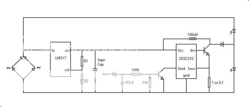
So, first I paste a corrected version including the shutdown circuit from your post 76:
Tested combinations:
a) R1 - 150 ; R2 - 100 ; Supercap: Taiyo 2.3V 4.7F
b) R1 - 180 ; R2 - 200 ; Supercap: Maxwell 2.7V 10F
Please point out any mistake, as I m a total newbie.
looks like the right values for the capacitor voltage ratings.. so far, so good.
Now my questions:
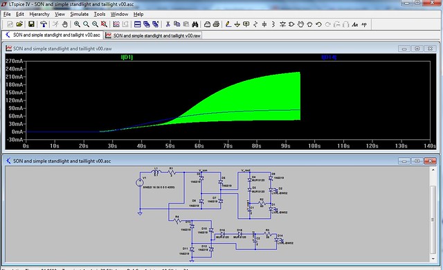
1) I would love to extract all juice posible, but I'm currently not sure if the shutdown circuit is working, how do I check?.
Regarding how to check to see if the shutdown circuit is working... the obvious answer is to short the pin to ground and see if the boost convert stops running.
However, in the 9 years since that thread took place, I've had a chance to build a somewhat similar circuit. I've learned that the LED will still conduct current through the boost converter's inductor if the supercap is charged to 2.5V or so. It's just a dim glow, but it surprised me.
I also realized that the voltage across the lower LED will charge the supercap to the LED's forward voltage (usually around 3V). To prevent this, I added a schottky diode in series with the boost converter's output.
I have a suspicion that your question might be more like "why doesn't the boost converter run? Is the Shutdown function activated?". In that case, which is pretty common, since nothing ever works when you first build it, is to go back to the basics. Is there at least 1V at the Vcc pin? Is everything really connected to what you think it is connected to? This is the time to get out the meter and check everything... check resistance from end to end of things that should be connected. Check the voltage at each pin of everything and write it down on the schematic. Does it all make sense?
I can see no difference (sometimes I even think the standlight is shorter), I've also tried to omit the diode and connect instead a jumper from the + in the bridge rectifier, but it seems to shutdown the light while standing, any idea why?
which diode are you referring to? Is it the upper LED in Alex Wetmore's circuit in post #73? Looking at the schematic now, I suspect that if the upper LED was removed, then the input to the LM317 will be limited to 3V, since that is the voltage across the lower LED. Roughly 2V is dropped across the LM317 (more or less), which would only leave a volt or so to charge the supercap. Of course, the voltage across the LED will also cause current to flow backwards through the inductor (if the converter is shutdown), so that would allow the cap to charge up.
2) I remember an old Busch&Muller Oval that used a PowerLed while cycling and a smaller led (not useful to light the road but good enough as a "be seen") for standlight i remember that it was quite durable. I have the feeling that it would be easy to adapt this idea and modify this circuit and make the standing light use a different, smaller led for the standing function that only would be on while standing (exactly when the main led would be off) and so make it last much longer, so:
* would this change make the stand light last longer?
* what components would be suitable? I remember having read about super bright thru the hole leds somewhere in this forum.
* what changes should I make to the circuit?
thx, pbrena
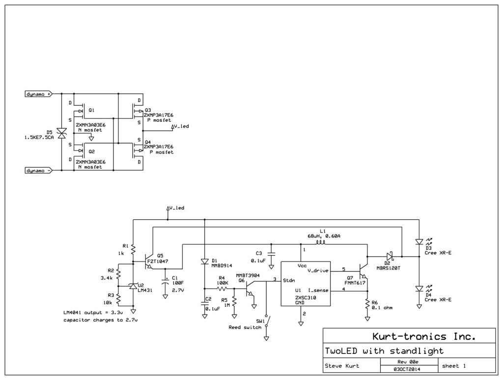
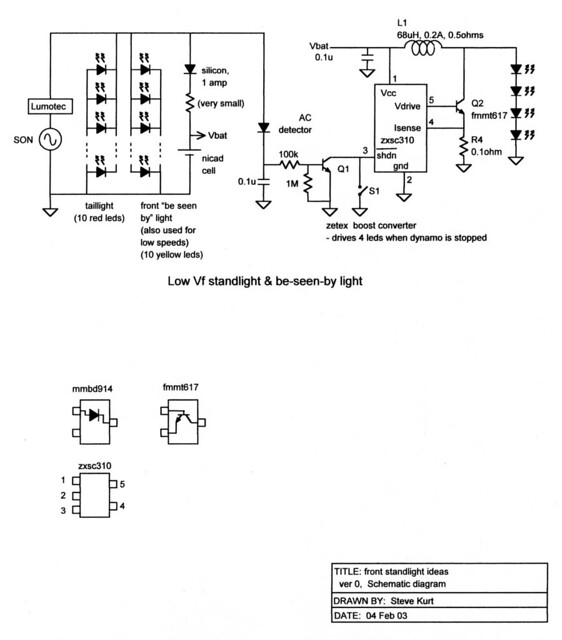
Using 5mm LEDs for the standlight is fine too. That's what I did for my first standlights (back when the headlight was incandescent!). I also do it for the taillight. In my designs, I was using red LEDs in the back, and yellow LEDs in the front (I don't think white LEDs were common yet). To use white LEDs, you'd probably just use two in series, instead of the 4 LEDs that I used.
Here's the schematic....
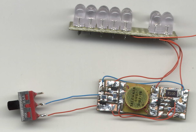
and this is what it looked like when it was built up.. not pretty, but it worked for many years (and probably still does)

")