I needed to make a li-ion charger for my brother as I am sending a Q3 and PR123/R123. So instead of making an AA holder, I decided to mod the JSB123 charger for him. My initial mod was to put a li-ion cell protection chip and it did work, but why not modify it to house a LTC4054 based charger as used by this DIY charger.
As I am sharing the process of mod I did, it will bring some technical information on JSB123 (4.2V) charger and also other things such as LED charging status indicator and FET reverse cell protection. I hope it can be useful for others.
JSB123 4.2V Charger
This circuit is very cleverly designed buck switcher and transisotr based linear regulator combination to produce 4.25V DC output from input 12V (16V+ rectified) DC. The power supply sayd max 600mA and the charger says 350mA charging current. It is about 0.5C for R123, but the charger actually delivered 200mA only. Both battery holders are joined parallel, no individual control.
The green led is tied permanently to the output (on all the time) and the red led is turned on by a PNP transistor by sensing current passing through a diode. So at starting of the charging the red led is bright and as the charging current drops, the red led gets dimmer.
This is typical charging process. Since the charger output is just 4.25V, it may not trigger the over-charge protection circuit like Pila, so it takes a lot longer time to charge and you may not know when the charging is completed.
I did a few changes to the existing circuit to accomodate the LTC4054 charger chip. I didn't have time to prepare the detail circuit of the JSB charger change, but if many cpfers want, I may start a seperate thread about the JSB charger.
- changed input polarity protection diode from parallel to serial to the DC input
I wonder why it is designed this way.
- added 10k resistor to the feedback divider, so the DC output is now 4.65V instead of 4.25V
The reference voltage is 1.25V so it was easy to calculate.
- added 2 3.3 ohm (1.65 ohm) to the current sensing resistor hoping the max current will jump
I managed to get 300mA max but no more, maybe the inductor or the main power supply capacity?
- connected 15K resistor from PNP transistor base to LTC4054 charge status output pin
Since the LTC output is open drain, it is just so nice to find a PNP transistor based led driver already built in so that I can source the current to the bi-color led instead of sinking.
- added a capacitor and resistor to the DC output of the linear regulator
There is about 2V drop by the 2 transistor regulator and 1 current sensing diode and I find something funny which I can't understand with my limited knowledge. When the power is on, the buck chip didn't oscillated and the it did only when there was a slight output current draw. Somehow the LTC4054 chip didn't trigger the regulator and I had to add a 10K resistor to the regulator output to draw some current and it is stable.
LTC4054 Charger
Since there is some space on top of the existing board, I fixed all the components on top, the spider style.
I didn't have 3.3K SMT resistor, so hooked 3 10K resistor to get 300mA max constant charging current. Also added Vishay SI2314EDS N-channel FET as reverse cell protection as suggested by Doug_S, it works!
A typical charging of JSB123 with this charger is as follows. No major big deal, but just works as expected. Compared to the above charging data.
Charging Status led
Many cpfers asked me how to determine if the charging is complete with LTC4054 charger since the led seems on all the time.
The charging indicator pin of LTC4054 is open drain and it works like mechanical switch to allow current pass through, it does not provide current by itself.
While it is charging, the pin will sink as much as 20mA and the led is very bright. When the charging is complete, it still let 20uA current pass through instead of total cut off. The total cut off is done to indicate the shutdown status when the output voltage is higher than input such as battery is in but no power supply connected.
Even with small current such as 20uA, a bright led will still show some light and it may be mistaken as led on with charging. One way to overcome this is to use a dimmer discrete led display which will not show light at low current.
I and my buddy
cgpeanut (Roberto) have discussed about the desire to have red light for charging and green when charging is completed. We went further using a PIC micro-P to monitor the charging current and the battery voltage to indicate different charging statges with different led light pattern or color. I will write a program for PIC to do this sometime later.
Then I got wild to think of using the PIC to control the whole charge process without using a charger chip. It is possible and also feasible to make real intelligent charger. But I recognize it only suitable as school project, not really for a commercial project. There it goes!
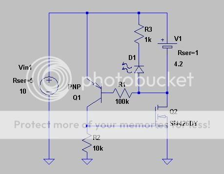
Meantime, here is a PNP transistor based high side switch to source the current to led based on the signal from the LTC4054. It is especially suitable to provide current to common cathode bi-color led.
R1 (330 ohm) is used since it is already in the original charger and it gives very nice brightness red light, it may be increased.
R2 (2.2k) is also already there, sos didn't want to change. But the R3 (15K) is what I put and I find it working very fine to clearly distinguish between charging and complete. You may want to change value between 10K and 20K for best result depending on the transistor and R2 value.
Reverse Cell Protection
This N-channel FET based protection circuit is made by Doug_S and MrAl has drawn the circuit together with explanation of theory of working. Since I am not the one to use this charger, but my brother, so I thought a reverse cell protection is important.
As suggest, I used very low Rdson FET Vishay Si2314EDS and built in to the charger. Boy, it was really hard to buy this FET. Thanks to
Jay for helping me to get.
The reverse cell indicator led is built into the holder with 100 ohm current limit resistor. This low value gives quite bright red light even with much depleted cell when inserted reverse. It takes about 20mA from the fully charged R123 when inserted reverse without power connected.
Now the time has come for real test!
I connected power supply and with my fingers crossed, I inserted a fully charged R123 reverse. Both charging indicator and reverse cell indicator led were lit. The current measurement from the battery is 50mA only. Thanks God!
I shorted the both output terminal of the charger and measured the current and got 30mA. So total 50mA is correct.
The LTC4054 has output short circuit protection and I presume 30mA limited current is controled by the chip. Some brave souls may want to try this without the FET protection.
Done
It is done! I like it very much, but it is good to know my brother is going to enjoy it. It charges both 14500 and R123 with 2+ hours to complete.
I will update the main post with the new led indicator and fet protection when I find time.
-- dj