Surefire L2 with Cree MC-E

LLCoolBeans

Flashlight Enthusiast
Joined
Apr 18, 2008
Messages
1,040
Location
Arizona
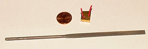
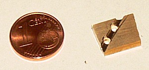
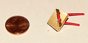
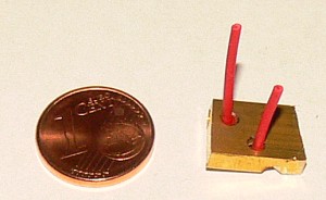
I intend to use thermal compound to attach the body of the emitter to the riser. Once that is centered I'll solder the emitter legs directly to the riser to make the jumper connection. Then I'll solder a couple of 24ga wires to the airborne legs for the positive and negative connections. After that's done, press the emitter into place smear everything with compound and insert heat sink.

This is my first modding project, so if I'm doing something wrong please speak up.

Thanks
 

Energie

Enlightened
Joined
Nov 12, 2006
Messages
302
Location
Germany
One question: how's the donut? Is there an X-shaped null void at the center?

The "X-shaped donut" is slightly visible at short distances (1-2 feet) on a white wall.

MC-E, distance 3 inch (SF L2 on high)
MC-E4.jpg


MC-E, distance 10 inch (SF L2 on low, pic underexposed)
MC-E5.jpg


LLCoolBeans:
I´ve seen your question about soldering in the machining section.
Silver is an excellent heatsink.
But there is a problem. The thermal paste between the silver heatsink and the MC-E leads the heat from soldering direct to the dies. I think, more than 1-2 seconds soldering may damage the MC-E.
 

LLCoolBeans

Flashlight Enthusiast
Joined
Apr 18, 2008
Messages
1,040
Location
Arizona
I´ve seen your question about soldering in the machining section.
Silver is an excellent heatsink.
But there is a problem. The thermal paste between the silver heatsink and the MC-E leads the heat from soldering direct to the dies. I think, more than 1-2 seconds soldering may damage the MC-E.

Dang! That throws a monkey wrench into the works. It's definitely going to take more than 1-2 seconds.

I guess there's one way to find out for sure. :sweat:

Anyone else have an opinion on this? Am I going to cook the emitter trying to solder the legs to the silver riser?
 

mudman cj

Flashlight Enthusiast
Joined
Dec 14, 2005
Messages
1,827
Location
Where corn and pigs are grown unimpeded by trees
Its not advisable. But, you could insert a thin heat shield between the silver and the LED thermal pad while you solder, then remove the shield, work thermal grease/adhesive into the gap, and press into place. This will bend the LED leads slightly, but will not break them. The hardest part will be working the thermal grease/adhesive into the gap.
 

LLCoolBeans

Flashlight Enthusiast
Joined
Apr 18, 2008
Messages
1,040
Location
Arizona
Its not advisable. But, you could insert a thin heat shield between the silver and the LED thermal pad while you solder, then remove the shield, work thermal grease/adhesive into the gap, and press into place. This will bend the LED leads slightly, but will not break them. The hardest part will be working the thermal grease/adhesive into the gap.

That would be more work than just doing away with the riser/jumper combo altogether and using a wire like Energie did. The only reason I thought of the idea was to make less work for myself and not have to change any of the original components. I can always just cut off the little ears on my riser and drill two additional holes in the heat sink for the jumper wire. Looks like that may be what I need to do.

Dang! And I thought my solution was so slick. Oh, well, live and learn. It is my first mod after all.
 
Last edited:

Energie

Enlightened
Joined
Nov 12, 2006
Messages
302
Location
Germany
I think, a jumper wire is the way to go.
You can lead the jumper wire through the stock heatsink,
or:
drill two small holes and use a small file to make room under the silver heatsink.

MC-E6.jpg


MC-E7.jpg


MC-E8.jpg


MC-E9.jpg
 

LLCoolBeans

Flashlight Enthusiast
Joined
Apr 18, 2008
Messages
1,040
Location
Arizona
That's a fine idea, but I don't think my riser is thick enough to accommodate a groove deep enough to envelop a 24ga wire with insulation. This also would reduce the amount of surface aria in contact with the heat sink.

I'm going to rethink this tonight, but I'll probably just end up drilling two new holes in the stock heat sink.

Thanks for your help on this guys.
 

LLCoolBeans

Flashlight Enthusiast
Joined
Apr 18, 2008
Messages
1,040
Location
Arizona
Well, I got it all back together finally. I had a lot of trouble learning to solder wires to those tiny emitter legs. That was a lot more difficult than I had originally imagined. Got the hang of it eventually though, but there was one casualty. Luckily I bought two emitters.

Cut the ears off of my riser and used a jumper wire.

It's working now, but I'm not seeing any noticeable increase in brightness. It would appear to be about the same brightness as the Luxeon 5 was. Except for that the Lux 5 had a nicer tint and less artifacting. Dang! Did I do something wrong?

No doughnut but the X is pretty prominent.
 

DaFABRICATA

Flashlight Enthusiast
Joined
Jan 10, 2007
Messages
3,946
Location
Michigan
It should be noticably brighter than the LUX V.

I run mine on a single RCR and its still way brighter than a stock KL4.

Sounds like there may be a problem....are you using FRESH batteries?
 

LLCoolBeans

Flashlight Enthusiast
Joined
Apr 18, 2008
Messages
1,040
Location
Arizona
It should be noticably brighter than the LUX V.

I run mine on a single RCR and its still way brighter than a stock KL4.

Sounds like there may be a problem....are you using FRESH batteries?

Yea, that was the first thing I tried.
 

LLCoolBeans

Flashlight Enthusiast
Joined
Apr 18, 2008
Messages
1,040
Location
Arizona
It's a WD M bin. Spot appears white, maybe slight yellow tint. Spill is purpleish :green:. Old Lux5 had a nice even slightly warm beam.

Could something be shorting? I'm guessing if something was shorting, it just wouldn't work at all or work briefly then self destruct. I did solder and resolder the legs of the emitter to the wires several times before I got it right. Could I have over heated it when soldering? What if I got the polarity reversed? It's a diode so electrons should only flow one way, right?

Dang.
 
Last edited:

Energie

Enlightened
Joined
Nov 12, 2006
Messages
302
Location
Germany
Remove the tailcap of the light.
Use a multimeter, one tip on the light-body, the other on the "-" contact of the battery.
Current should be at 1,0 - 1,1 A (two fresh 3V batteries).
 

LLCoolBeans

Flashlight Enthusiast
Joined
Apr 18, 2008
Messages
1,040
Location
Arizona
Remove the tailcap of the light.
Use a multimeter, one tip on the light-body, the other on the "-" contact of the battery.
Current should be at 1,0 - 1,1 A (two fresh 3V batteries).

I'm reading 1.25, what does that mean?
 

Energie

Enlightened
Joined
Nov 12, 2006
Messages
302
Location
Germany
Perhaps the batteries are not new. 1,25 A with used batteries is ok so far.
If the MC-E is wired correct (and without a short) I suspect it has been damaged during the soldering.
The MC-E is far brighter than the Lux5 (see post #1).
 

LLCoolBeans

Flashlight Enthusiast
Joined
Apr 18, 2008
Messages
1,040
Location
Arizona
The WD M bin I got from Kaidomain.

I have a couple of 5As coming in any day now. I was going to try again with one of those. I have to assume that I overheated the emitter while soldering it, since that is the only info I have to go on.
 

Icarus

Flashlight Enthusiast
Joined
Nov 1, 2003
Messages
3,495
Location
Belgium
The WD M bin I got from Kaidomain.

I have a couple of 5As coming in any day now. I was going to try again with one of those. I have to assume that I overheated the emitter while soldering it, since that is the only info I have to go on.

:thanks: keep us updated about your mod. :thumbsup:
 

Latest posts

Top