DIY LED circuit help

draaz1

Newly Enlightened
Joined
Jun 26, 2014
Messages
3
Hey guys just looking for some help with the LED diagram I put together. I'm a MechEng so not very much confidence on the EE side. Any help is greatly appreciated.

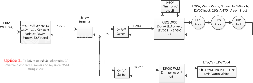
I am trying to design a system with both LED pucks in series and String lighting, both being individually dimmable. The pucks will illuminate individual display cabinets and the string for a large open area.


  1. Is the attached diagram arranged correctly to achieve the desired result?
  2. Do I need a heat sink?
  3. Are there different products I should be using?

Many thanks for the help guys!

Drawing1_zps201ce5c1.png
 

Conte

Enlightened
Joined
Dec 15, 2009
Messages
735
Location
Canada
I'm an electrical tech so I might have some insight.

Why are you stepping up to drive the Pucks in series when you could run them in parallel and not need to step up.
Also 12x3 is 36v, and the flexblock is rated for 48v. Unless it's adjustable you're over volting those pucks. 16v each which they may not handle.

I'd would run them in parallel and use the same PWM dimmer control you're using on the LED strip.

That's the only problem I'm seeing with this design.

I'd need to see specific data on those pucks, but if they are of a 12v design, chances are they have their own kind of driver inside and don't need another.
I believe the flexblock is designed to run raw leds that do not have drivers.

What are you wondering you need a heatsink for ?
 

draaz1

Newly Enlightened
Joined
Jun 26, 2014
Messages
3
Thanks for the help Conte, I'll try to explain a little more.

I was going to step up to drive the pucks because I was told they work better with a constant current source (provided by the Flexblock). Regarding the driving voltage, the FlexBlock is a boosting driver, so it can output a higher voltage than the input voltage. With 12V input, when wired in the default Buck/Boost mode (as labeled on the driver), the maximum output voltage is calculated as 48V minus your input voltage. So, with 12V input, the FlexBlock can output up to 36V.

I don't want to run both the strip and the pucks off of one PWM dimmer as I would to be able to dim them individually. The Flexblock has dimming functionality for the pucks.

The pucks are just cheap 12V input ones with no driver inside. I was planning on using these.
http://www.amazon.com/dp/B00EJM7Y8Q/?tag=cpf0b6-20

I was just worried about excessive heat generation but it will probably be okay. Any other suggestions? Thanks again for everything.
 

jason 77

Enlightened
Joined
Oct 2, 2008
Messages
518
Location
cali
The pucks are just cheap 12V input ones with no driver inside. I was planning on using these. http://www.amazon.com/dp/B00EJM7Y8Q/?tag=cpf0b6-20

The LED pucks you linked to are designed to be hooked up in parallel to the wall wart that comes with the kit, it doesn't say what output that wall wart is putting out but it could be just 12vdc. I bet there is some form of current regulation built into each of those pucks, could be something as simple as a resistor or something a little more complicated as I can't tell from the pictures. I would ditch the flexblock driver you have in your diagram and go with another PWM dimmer like the one you have for the LED light strip. Also why do you have a on/off switch for each line when you diagram indicates the both the PWM dimmer and flexblock have "dimmer/w on/off" already?
 
Last edited:

draaz1

Newly Enlightened
Joined
Jun 26, 2014
Messages
3
I'm not partial to those particular LED pucks if you think if would be better to use something else. Sounds like you guys are suggesting the layout below? Is the return wiring from the pucks okay in this configuration?

Drawing2_zps630d6496.png
[/URL][/IMG]
 

Conte

Enlightened
Joined
Dec 15, 2009
Messages
735
Location
Canada
Yeah, that looks good.

Return wiring?
Its'not labeled, but doesn't matter.
Mind your polarities and you'll be fine.
 
Top