loneoceans
Newly Enlightened
- Joined
- Jan 8, 2017
- Messages
- 9
Hello all and glad to join everyone here at Candle Power Forums. Here's a weekend project that turned out pretty nice and I thought I'd share.
TL;DR:
As of right now the main functionality is working and I hope to tidy up the V1 of this driver and release it open source for all to use") . In addition, I'm also writing up a detailed page on its operation and hope to publish it on my webpage soon (www.loneoceans.com/labs/).
. In addition, I'm also writing up a detailed page on its operation and hope to publish it on my webpage soon (www.loneoceans.com/labs/).
Introduction & Problem
This project was motivated by the desire to:
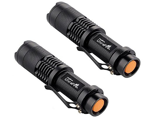
These flashlights had space for a 20mm PCB driver board, so I decided to design a driver around this constraint and to replace the XML LED from the flashlight (using the same heatsink since they have the same footprint as the XHP50 in 6V configuration), and also to replace the driver with my driver. The goal was to build a simple ~1500 to 2000 lumen single-cell flashlight at a low cost!
The result is a the GXB20 driver – G after my name, X referring to the XHP50/70-series LEDs, B being a boost driver and 20 being a 20mm driver.
Design and Operation
Since I was going to be designing the board from scratch, I figured that the main things I wanted was:
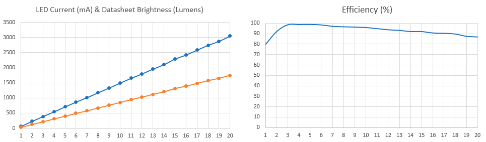
For adjusting brightness, a simple way and what is often done is to have a fixed boost voltage, run the LED across a current limiting resistor, and then use a FET and PWM to control LED brightness. This works OK, but due to the V_fwd inconsistencies of LEDs, this can lead to widely differing LED brightness. In addition, PWM generates flashing/strobe effects, which is not as pleasant as a true constant-current limiting circuit. After some thinking, I came up with a simple method - the LED I_fwd current is constantly sampled across a small current-sense resistor. This value is then amplified via a digitally variable amplifier (controlled via an Attiny84A) and fed into the boost power circuit. The boost circuit then regulates the voltage to maintain the desired current!
Next for programmability, I decided to go for an Atmel ATtiny84A instead of an Attiny85 due to the fact that it came in a very small 3x3mm QFN package, has EEPROM for storage of memory modes, allows me to use the hobbyist-friendly Arduino environment for sharing / open-source, and comes with a lot more GPIO for additional features.
These new features includes things like battery sensing (so I can turn off the LED drive if the battery voltage falls too low), as well as real-time temperature sensing for dynamic LED brightness control if it gets too hot.
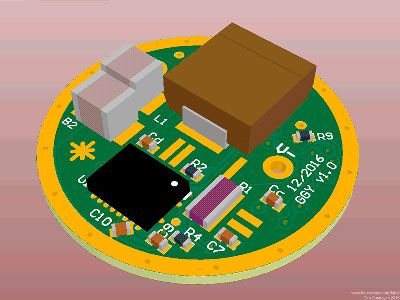
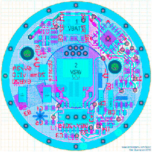
So late last December during a somewhat boring weekend, I sat down and quickly came up with a design, did up the schematic, created a board layout and sent the PCBs to be made. Over the last week, I finally got the PCBs and components, quickly assembled them, and wrote some initial firmware to test it! Now looking back, the board -does- still have some space left, so a 17mm board might be possible too…
Programming and Testing
Soldering this together with traditional tools is possible with a bit of practice, but I was able to get access to a bench microscope which helped a lot! :laughing:
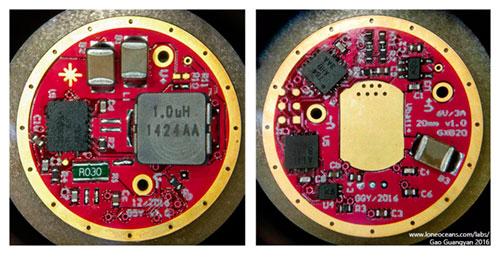
Together with needle-nose tweezers and a small-tip soldering iron, I was able to put together the PCB without too much trouble. After-all, the smallest component on board is a 0402 resistor/capacitor, so it's actually quite doable by hand. The small ICs are probably easier done via hot air or via very small soldering irons.
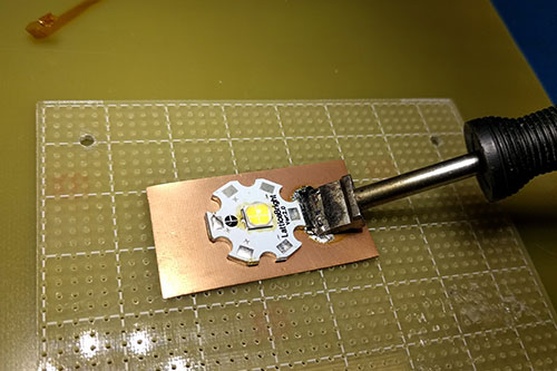
Next, I used a copper-plate and a large soldering iron to reflow the XML LED off the star-heatsink which came on my cheap Amazon LED flashlight. I replaced it with a 90CRI XHP50 LED from Cree. Then I soldered it up to the main driver board. Notice I also reused the spring on the original driver board and moved it over to the new one.
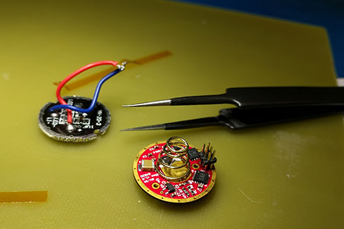
For programming, I'm using the standard 6-pin AVR ISP 2 programming header. The default header is very large at 0.1" pitch, so instead I made a 0.05" 6-pin 'adapter' using a 0.05" 6-pin female header to a 0.1" pitch header.
Notice that the driver board has 6 pads for soldering on a 0.05" header. For this developmental board, I simply soldered the header on (which I can desolder later). Once I finalize the firmware, I can simply press-and-hold the header onto the pads during programming of the microcontroller.
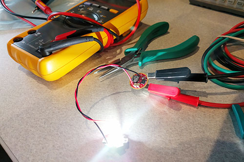
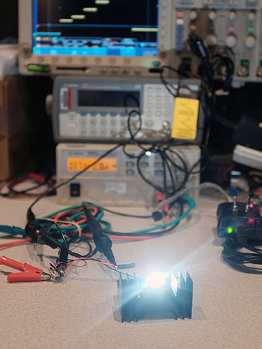
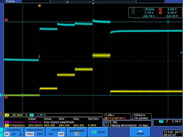
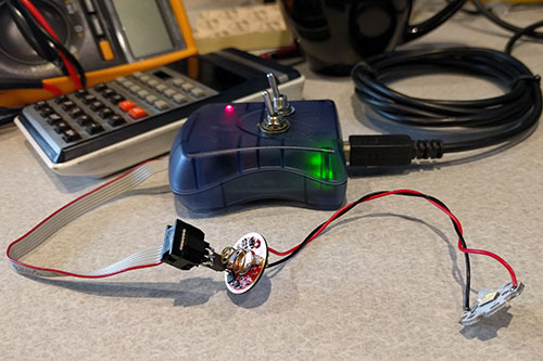
Finally I did a quick test – in short, it all seems to work great!
Right now, I'll be mostly working on firmware and verifying its operation, as well as hopefully adding some interesting effects such as 'candle-mode' etc..
This project turned out to work out quite nicely even though I only spent a short weekend on it! As a result I'm sure there are a lot more improvements and things to change which I can make in upcoming revisions, and I appreciate any thoughts comments and suggestions!
More to come soon and stay tuned on this thread for updates as I continue to work on the GXB20!
TL;DR:
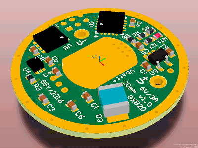
I designed and made a simple constant current single-cell (e.g. 18650) XHP50/70 (6V 3A) Programmable Boost LED Driver. I've called this driver the GXB20. This is a true constant current driver which takes feedback from the drive current and regulates the output to match the desired current. I designed the driver to have a 20mm diameter to fit cheap 18650 LED flashlight hosts from Amazon/Ebay. The driver is fully programmable with an on-board ATtiny84A and includes other features such as temperature sensing and cut-off, LED brightness adjustment via constant-current limiting (no more PWM flickering!), battery voltage sensing, memory for various modes, and is designed to be able to supply the full 6VDC 3A output with ~95% efficiency via a boost circuit running off a single 3.7V lithium battery.
As of right now the main functionality is working and I hope to tidy up the V1 of this driver and release it open source for all to use
. In addition, I'm also writing up a detailed page on its operation and hope to publish it on my webpage soon (www.loneoceans.com/labs/).Introduction & Problem
This project was motivated by the desire to:
- Use some of the new XHP50 LEDs from CREE which are not only ridiculously bright, up to 2000 lumens per package, but also comes in high CRI (>90) bins
- Run this LED from a compact, single lithium-cell flashlight. The main problem with this is that the XHP50 LEDs require 6V or 12V (depending on wiring configuration), and this requires a boost circuit to produce the 6V from the 3.5-4.2V from a single-cell 18650. In addition, the XHP50 LED can take up to 3A of drive, so the driver needs to be able to support 18W of power in a small package.
These flashlights had space for a 20mm PCB driver board, so I decided to design a driver around this constraint and to replace the XML LED from the flashlight (using the same heatsink since they have the same footprint as the XHP50 in 6V configuration), and also to replace the driver with my driver. The goal was to build a simple ~1500 to 2000 lumen single-cell flashlight at a low cost!
The result is a the GXB20 driver – G after my name, X referring to the XHP50/70-series LEDs, B being a boost driver and 20 being a 20mm driver.
Design and Operation
Since I was going to be designing the board from scratch, I figured that the main things I wanted was:
- (1) proper constant current operation and brightness modes
- (2) programmability
- (3) safety features (mostly over-temperature cut-off!).
For adjusting brightness, a simple way and what is often done is to have a fixed boost voltage, run the LED across a current limiting resistor, and then use a FET and PWM to control LED brightness. This works OK, but due to the V_fwd inconsistencies of LEDs, this can lead to widely differing LED brightness. In addition, PWM generates flashing/strobe effects, which is not as pleasant as a true constant-current limiting circuit. After some thinking, I came up with a simple method - the LED I_fwd current is constantly sampled across a small current-sense resistor. This value is then amplified via a digitally variable amplifier (controlled via an Attiny84A) and fed into the boost power circuit. The boost circuit then regulates the voltage to maintain the desired current!
Next for programmability, I decided to go for an Atmel ATtiny84A instead of an Attiny85 due to the fact that it came in a very small 3x3mm QFN package, has EEPROM for storage of memory modes, allows me to use the hobbyist-friendly Arduino environment for sharing / open-source, and comes with a lot more GPIO for additional features.
These new features includes things like battery sensing (so I can turn off the LED drive if the battery voltage falls too low), as well as real-time temperature sensing for dynamic LED brightness control if it gets too hot.
So late last December during a somewhat boring weekend, I sat down and quickly came up with a design, did up the schematic, created a board layout and sent the PCBs to be made. Over the last week, I finally got the PCBs and components, quickly assembled them, and wrote some initial firmware to test it! Now looking back, the board -does- still have some space left, so a 17mm board might be possible too…
Programming and Testing
Soldering this together with traditional tools is possible with a bit of practice, but I was able to get access to a bench microscope which helped a lot! :laughing:
Together with needle-nose tweezers and a small-tip soldering iron, I was able to put together the PCB without too much trouble. After-all, the smallest component on board is a 0402 resistor/capacitor, so it's actually quite doable by hand. The small ICs are probably easier done via hot air or via very small soldering irons.
Next, I used a copper-plate and a large soldering iron to reflow the XML LED off the star-heatsink which came on my cheap Amazon LED flashlight. I replaced it with a 90CRI XHP50 LED from Cree. Then I soldered it up to the main driver board. Notice I also reused the spring on the original driver board and moved it over to the new one.
For programming, I'm using the standard 6-pin AVR ISP 2 programming header. The default header is very large at 0.1" pitch, so instead I made a 0.05" 6-pin 'adapter' using a 0.05" 6-pin female header to a 0.1" pitch header.
Notice that the driver board has 6 pads for soldering on a 0.05" header. For this developmental board, I simply soldered the header on (which I can desolder later). Once I finalize the firmware, I can simply press-and-hold the header onto the pads during programming of the microcontroller.
Finally I did a quick test – in short, it all seems to work great!
Right now, I'll be mostly working on firmware and verifying its operation, as well as hopefully adding some interesting effects such as 'candle-mode' etc..
This project turned out to work out quite nicely even though I only spent a short weekend on it! As a result I'm sure there are a lot more improvements and things to change which I can make in upcoming revisions, and I appreciate any thoughts comments and suggestions!
More to come soon and stay tuned on this thread for updates as I continue to work on the GXB20!