georges80
Flashlight Enthusiast
Might as well start a new thread for the hi power Flex proto.

The thermal pad material that I used is available from Mouser. About US$22 for a sheet, so rather spendy, but given how well it works and how little is typically needed I think it is reasonable value and useful to have in a modder's drawer.
http://www.mouser.com/Search/Refine.aspx?Keyword=861-TGF150D
I am very impressed how well the material works, it is very pliable and conforms well to the surface it is on. It is not sticky, but it acts as if it is tacky and if pressed between a heatsink and Star etc. it does 'hold' the item in place. Obviously some further mechanical attachment method would be highly advisable. Mouser also has a few different grades available (price varies depending on thermal conductivity).
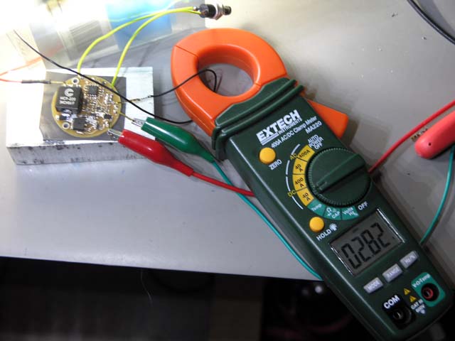
hipFlex is at the proto stage right now, I am on the 2nd revision, mainly changes in layout and power FET. Rev2 appears to work very well, I ran it 2 hours with no airflow, just mounted on the aluminium using the thermal pad material and it never got more than warm (maybe 30C with 20C ambient). The 3 P7's did get hot (~28W input power to them) - well, the larger chunk of aluminium they were on got hot and so had a fan keeping things stable.
The design of the board has two mounting holes to provide a way to 'squeeze' the thermal pad material between the heatsink and the bottom of the PCB which is the thermal interface (lots of thermal vias from the key 'hot' components). The board only has components on the top side to make it easier to mount the entire bottom of the board to a heatsink, though only the right 1/2 (approx) needs to be. The board is 1.4" in diameter, so not tiny, but then a multi P7 (or MCE) light is not going to be tiny anyway.
At this time I plan to support 4 current tables, 1A, 1.5A, 2A and 2.8A). For <1A just use a bFlex or nFlex.
Initial efficiency measurement with ~16V in and ~10V out (3 x P7) at 2.8A out shows just over 92% which is pretty good in my books.
The hipFlex has reverse polarity protection, temperature sensing, input voltage sensing and essentially the entire UI-uni firmware base that is on the other Flex drivers - so nothing new to learn there.
There is more testing to do and tuning of current tables/levels before I commit to do a production run of boards.
I'm also trying to gauge the interest in such a driver. My aim is to price it ~ $35 and provide a piece of the thermal pad material.
cheers,
george.


